


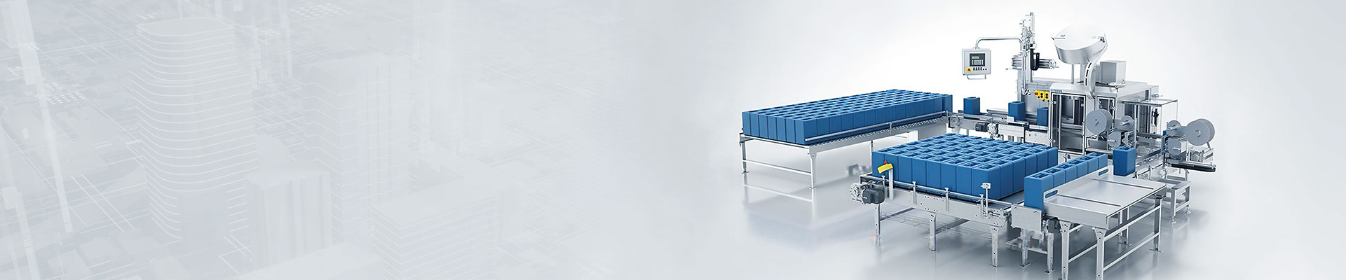
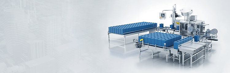


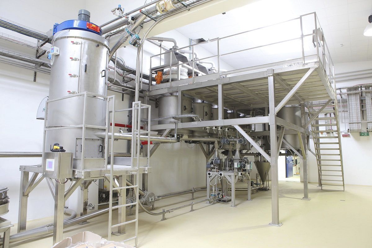
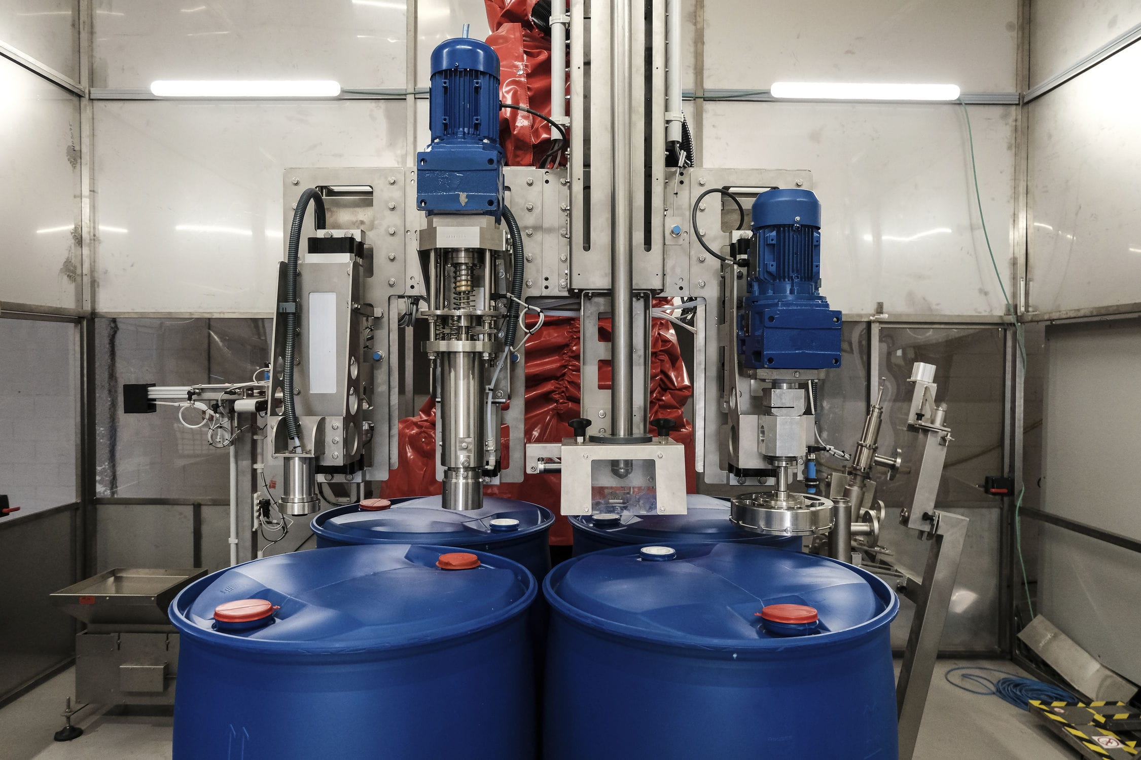


The feeding system selects the target value of dosage according to the process formula, sets the discharge quantity of each material through the weighing controller, and stores the formula, after pressing the START key, the PLC sends out the dosage instruction, at this time, the screw feeder starts to dosage, the valve of the intermediate dosing hopper closes, the material falls into the dosing hopper, and the valve of the liquid material hopper opens, when the weight of the material reaches the target value, the weighing module group sends out a signal to the weighing When the material weight reaches the target value, the weighing module group will send a signal to the weighing instrument and PLC will issue a command to stop feeding, at this time, the screw feeder will stop working.

 020-34563445
The batching machine mainly needs to be accurately controlled according to the data returned from some analog Weighing modules and digital weighing modules, which are collected from 20 analog quantities including 6 levels of material conveying volume, 6 levels of material weighing weight, drying cylinder temperature, volume and temperature. Switching quantity inputs such as feeding, material door interlock, powder door interlock, bucket door switching position, mixer, inclined belt, flat belt operation, system allowable weighing, unloading and so on. Switching outputs include each material gate feeding motor relay, each screw machine switch, pneumatic valve, plus dose pump, each weighing bucket door opening, mixer door switching, etc.
The dual redundant central control computer, the highly reliable embedded lower computer and the industrial Ethernet that connects them together form the framework of the entire control system. The central control computer is responsible for the management and sending of the overall measurement and control information, and under the control of the operating system and application software, it completes the functions of human-machine interface display, data analysis and processing, data recording, monitoring, alarming and printing.
The central control machine of this feeding system adopts dual redundant embedded 32-bit computers of A and B machines, and the two machines work at the same time. Due to the directionality of Ethernet frames, the frames sent by the lower computer to A machine generally cannot reach B machine, so the system adopts programmable Ethernet switches, which have the function of port copying, i.e., each packet sent to A machine is copied to B machine. Nevertheless, as a backup machine, machine B should still be isolated from the network through a dedicated packet filtering routing software, this route by splitting the packet to determine whether the packet can pass, for machine B, normal operation only allows the measurement and control of the Ethernet information on a single transmission to the B, that is, the route closes the channel to the measurement and control of the Ethernet machine B. A, B machine through the dedicated Ethernet channel and heartbeat algorithms to monitor each other's work situation. A and B monitor each other's work through a dedicated Ethernet channel and heartbeat algorithm. In case of abnormal operation of the other machine, it instantly replaces the other machine.
The feeding system evaluates the other party's health and network condition by the time the other party's reply message is returned. when A fails, the reply packet time will exceed the pre-set timeout value T0, which triggers the A-party failure message from machine B, and machine B starts to take over the work of machine A. The packet filtering route (also called packet filtering firewall, packet filtering gateway) of machine B opens, and the packet filtering route of machine A closes, and the open/close time only The open/close time only takes up a few clock steps of the central control machine, so it is all in the microseconds. While allowing the packets input to the measurement and control Ethernet to pass through to the B machine and at the same time blocking the path to the A machine, the B machine records and alarms in a timely manner, and continues to receive test quantities sent by the sensors and sends commands to the actuators.
Unlike the failure of machine A, there is no need to open the packet filtering route when machine B fails, as long as machine A alarms to notify the failure information and record it. The dual redundant Ethernet switches are industrial Ethernet switches that act as network switching centers for transmitting network frames in the shortest possible time and ensuring minimal frame conflicts and packet loss. The lower node machine with data acquisition, conversion module and Ethernet controller adopts the architecture of ARM7CPU plus DM9000A, which is responsible for acquiring analog and switching quantities, adding sensor flags to the acquired data (with IP address as the flag), and then packing and uploading them. And the control information is received and unpacked, and distributed to the control terminal according to the control flag. The Ethernet communication circuit is mainly composed of network control chip, network transformer and E2ROM memory.
The network control chip DM9000A is the core of the lower node machine for Ethernet communication. It has 10M/100M communication rate. Network transformer PH163530 is to convert the data transmitted from the Ethernet into level signals matching with the Ethernet control chip.E2ROM memory mainly stores some parameters that need to be saved in the power-down of Ethernet communication, such as the local P address. The output control part consists of D/A analog output and digital switching output. the D/A output signals mainly control some analog input devices, and these signals are generated by the 10-bit D/A converter inside the CPU under the control of software. The digital switching output circuit can control external devices with higher power, such as conveyor belt motors and fans.


