


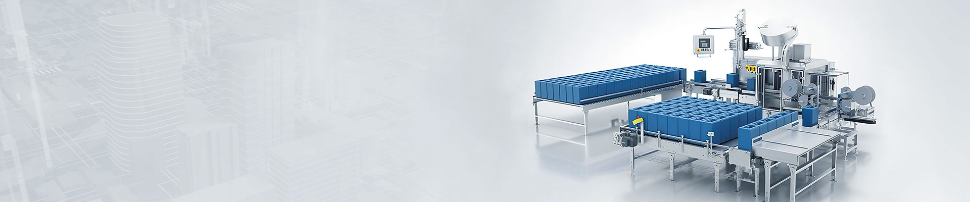


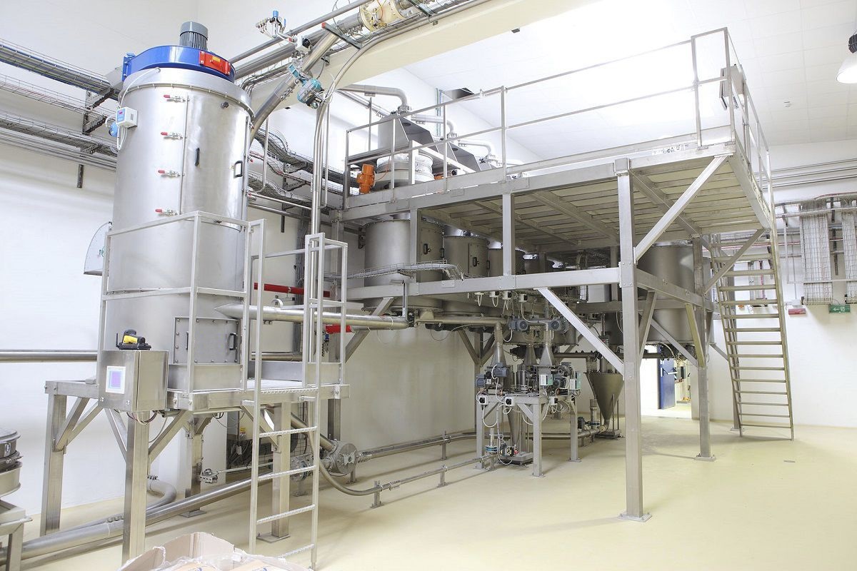


The peristaltic electronic floor scale adopts a self-developed precise feeding screw feeder as the feeding equipment. The screw feeder is equipped with a buffer bin by itself, and the buffer bin is provided with stirring blades, which can effectively prevent the material from clumping and arching. The screw conveyor blades adopt a variable pitch design to control the material conveying height to gradually decrease from thick to thin, ensuring that the material is evenly, smoothly and accurately fed into the carrier of the weighing system. The weighing instrument serves as the human-machine interface of the entire system, completing all system parameter Settings, process monitoring and data recording. Another one serves as a slave station, relying on the master station, to be in charge of data setting and process monitoring in the rear control room.

 020-34563445
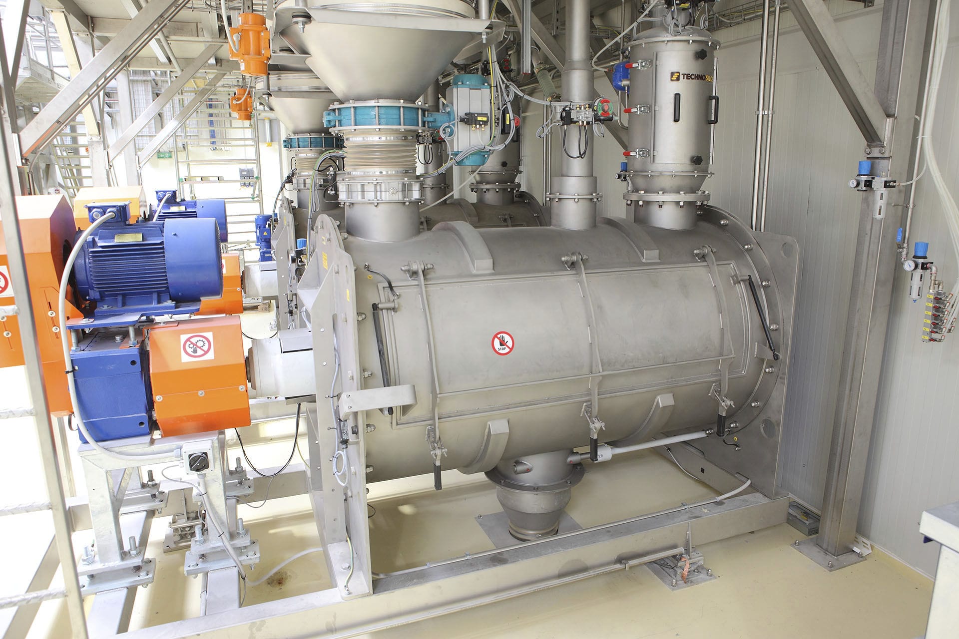
The peristaltic electronic floor scale adopts a sealed junction box and a dedicated industrial process weighing instrument. It communicates with the central control room through the RS485 bus. It can be independently controlled or connected to the PLC for control. The signals of each valve position and the position of the unloader are detected. It is mainly composed of several major elements such as the power unit, buffer chamber, stirring device, screw main shaft and quick shut-off gate. The self-developed precise feeding screw Feeder is adopted as the feeding equipment. The screw feeder is equipped with a buffer bin by itself, and the buffer bin is provided with stirring blades, which can effectively prevent the material from clumping and arching. The screw conveyor blades adopt a variable pitch design to control the material conveying height to gradually decrease from thick to thin, ensuring that the material is evenly, smoothly and accurately fed into the carrier of the Weighing system. The weighing instrument serves as the human-machine interface of the entire system, completing all system parameter Settings, process monitoring and data recording. Another one serves as a slave station, relying on the master station, to be in charge of data setting and process monitoring in the rear control room.
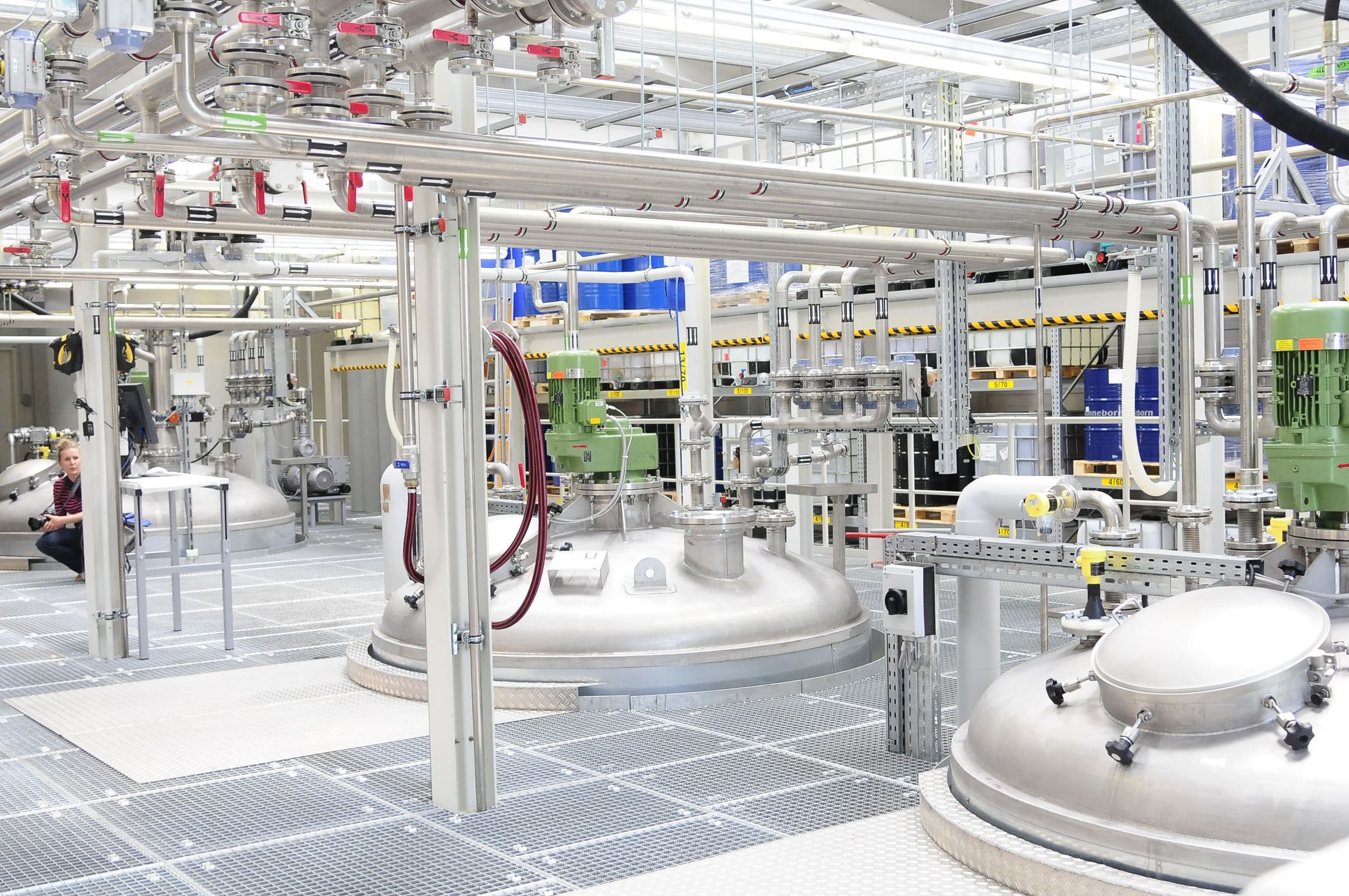
The electronic floor scale is composed of a touch screen, PLC, weighing instrument, frequency converter, vibrating motor, mixer, sensor and other components. The industrial control computer provides a human-machine interaction interface to complete functions such as inputting control information, data management, data display, storage, statistics and reporting. The weight of the ingredients is input through the touch screen keyboard. According to the proportion of raw materials, the weight of various materials is generated and transmitted to the PLC through communication. During the batching process, dynamic real-time monitoring is carried out. The detection and control system's other switch quantities sent by each slave machine are collected at regular intervals. The weight signals of each material are collected in real time and compared with the given signals to determine the next control scheme. At the same time, the weight signals are transmitted to the PLC.
The core equipment of an electronic floor scale is the precise weighing mechanism, which mainly consists of several major components such as the weighing unit, pneumatic actuator, load cell, base, flow aid air hammer and sealing cover. The weighing unit includes the weighing container, weighing shaft, shaft protection device, overload protection device, bearing and bearing housing, mounting plate, etc. The pneumatic actuator includes the swing cylinder Pneumatic solenoid valves and their accessories, etc.
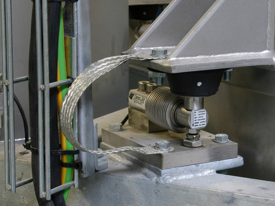
The electronic floor scale adopts the lever balance principle in mechanical dynamics, and selects high-precision micro-range Weighing modules. The tail end is fixed on the base, with the middle suspended. The upper part of the head end bears a set of meticulous and complex weighing components. The core component of the weighing components is the weighing shaft. The head end of the weighing shaft is connected to the weighing container through a key, and the tail end extends into the output shaft slot of the pneumatic actuator. However, without being connected to the output shaft, the pneumatic actuator must also be fixed on the base. The weighing component dominated by the weighing axis and the weighing container together form a completely enclosed and independent weighing unit. This weighing unit has sufficient freedom in physical space. When materials are weighed inside the weighing container, under the effect of gravity, the head end of the weighing module will slightly move downward. The physical deformation caused by the movement forms a linear proportional relationship with the weight of the materials. The load cell will convert this physical deformation into a millivolt output electrical signal through the working principle of the Wheatstone bridge and transmit it to the weighing instrument in the control system, ultimately achieving the purpose of automatic linear weighing.
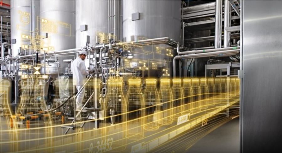
The electronic floor scale controls the PLC through the weighing instrument to drive the screw main shaft and the stirring shaft to rotate simultaneously. The materials entering the buffer bin are conveyed forward along the feeding pipe along the screw main shaft and guided into the pipe opening of the feeding pipe. After receiving the command, the cylinder extends the piston shaft to open the rapid gate, maintains it for a short period of time and then closes it quickly. During this short period of time, a certain amount of materials flow out of the pipe opening of the feeding pipe. The volume of material flowing out is related to the opening and closing time of the rapid gate and is precisely controlled by a computer program.
A helical main shaft is installed in the lower part of the buffer bin. The helical blades on the helical main shaft are variable in pitch. A motor and its reducer are set below the buffer bin as the power transmission device. The output shaft of the reducer is connected to a sprocket, which is connected to the double sprockets connected to the helical main shaft through a chain. The double sprockets are connected to the sprockets on the stirring shaft through a chain. A pair of stirring blades are provided on the stirring shaft. A feeding pipe is connected to the left side of the buffer bin. The part of the left end of the screw main shaft extending out of the buffer bin is fitted with the feeding pipe to facilitate the transportation of materials. A bracket is connected to the left end of the feeding pipe, and a cylinder is connected to the bracket. A rapid gate that cooperates with the feeding pipe is connected to the piston shaft of the cylinder. A guide rod is also connected to the bracket, and a spring is connected between the guide rod and the bracket. The other end of the guide rod is connected to the rapid gate, enabling the automatic control system to command the execution unit to complete the target action. The pneumatic actuator rotates the weighing shaft. The weighing shaft then drives the entire weighing unit to rotate, pouring the weighed material into the next process equipment. After receiving control instructions, it rotates the weighing unit back again to complete one cycle of action.


