


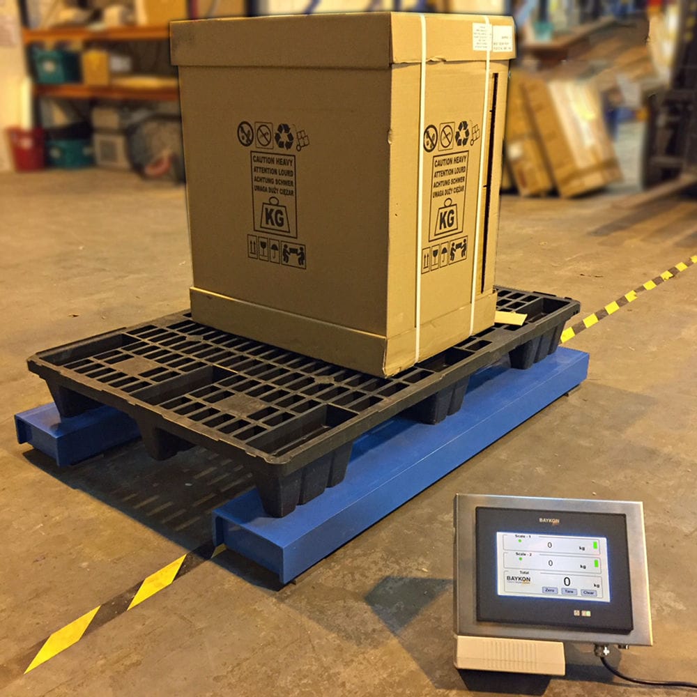


In the spiral batching machine, the material supply uses the inlet and outlet spiral. The spiral is driven by a variable frequency motor through a frequency converter. The system controls the running speed and start/stop of the motor based on the current weighing weight and the target weight. When the weighing weight reaches the allowable error of the target weight, the spiral stops feeding. The target weight for weighing can be obtained through a task call from the upper computer or directly inputted weight from the touch screen. Using the spiral motor, both lateral movement and feeding into the reaction vessel are achieved.

 020-34563445
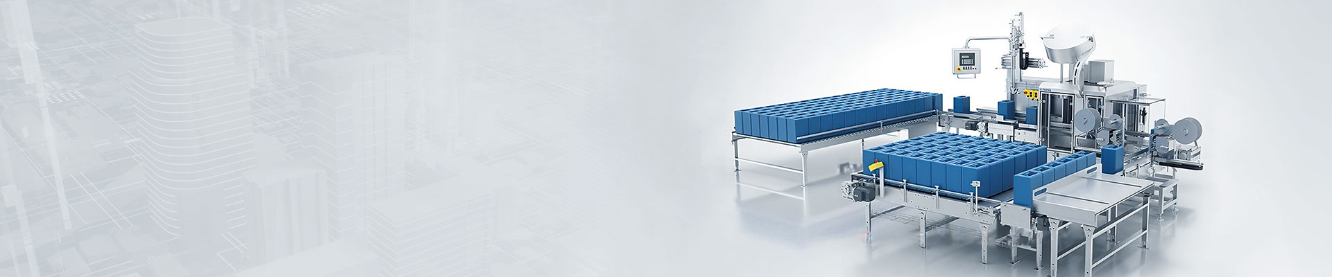
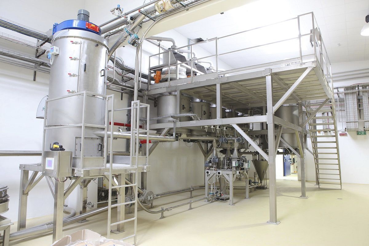
The spiral batching machine dynamically weighs and measures various materials according to the recipe, consisting of storage, batching, mixing, and discharging subsystems. It follows the production control process of batching according to the process flow. When entering the batching program, the batching first detects the reaction vessel to determine if it is less than the preset value. If it is less than the preset value, the material storage feeding device (for powder materials, it also needs to be conveyed through the feeding mechanism) is activated. The material enters the reaction vessel. The weighing module of the reaction vessel converts the measured dynamic data through an intelligent unit into A/D conversion and inputs it into the weighing instrument. The weighing instrument compares the collected dynamic weighing data in real time with the pre-set expected batching setting value (i.e., the mixing ratio parameters) using algorithms to control the batching and ensure the batching error. When the preset weight is reached, the controller immediately issues instructions to close the discharging device and the feeding mechanism. After all the materials are weighed, various materials are sent to the reaction vessel according to the set program and wait for mixing.
The Feeder controls the frequency converter through different combinations of output switch quantities to achieve variable speed regulation and rapid, slow, and fine feeding. At the beginning of the weighing, rapid feeding is carried out. When it reaches the predicted value for rapid feeding, slow feeding begins; when it reaches the predicted value for slow feeding, fine feeding begins; when the total weight of the feed reaches "target weight - pipe material weight - allowable error", feeding stops. The pipe material weight is the weight of the material remaining in the pipe after the motor stops rotating and flowing into the weighing tank. The percentage of the target weight is determined by the optimal value from the actual batching, and the target weight and allowable error are set by the touch screen.
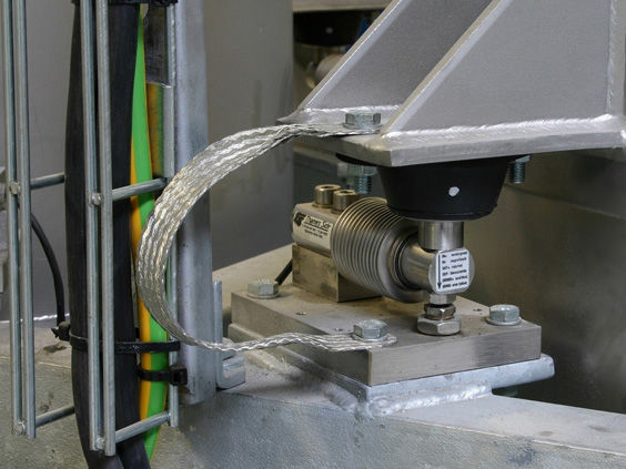
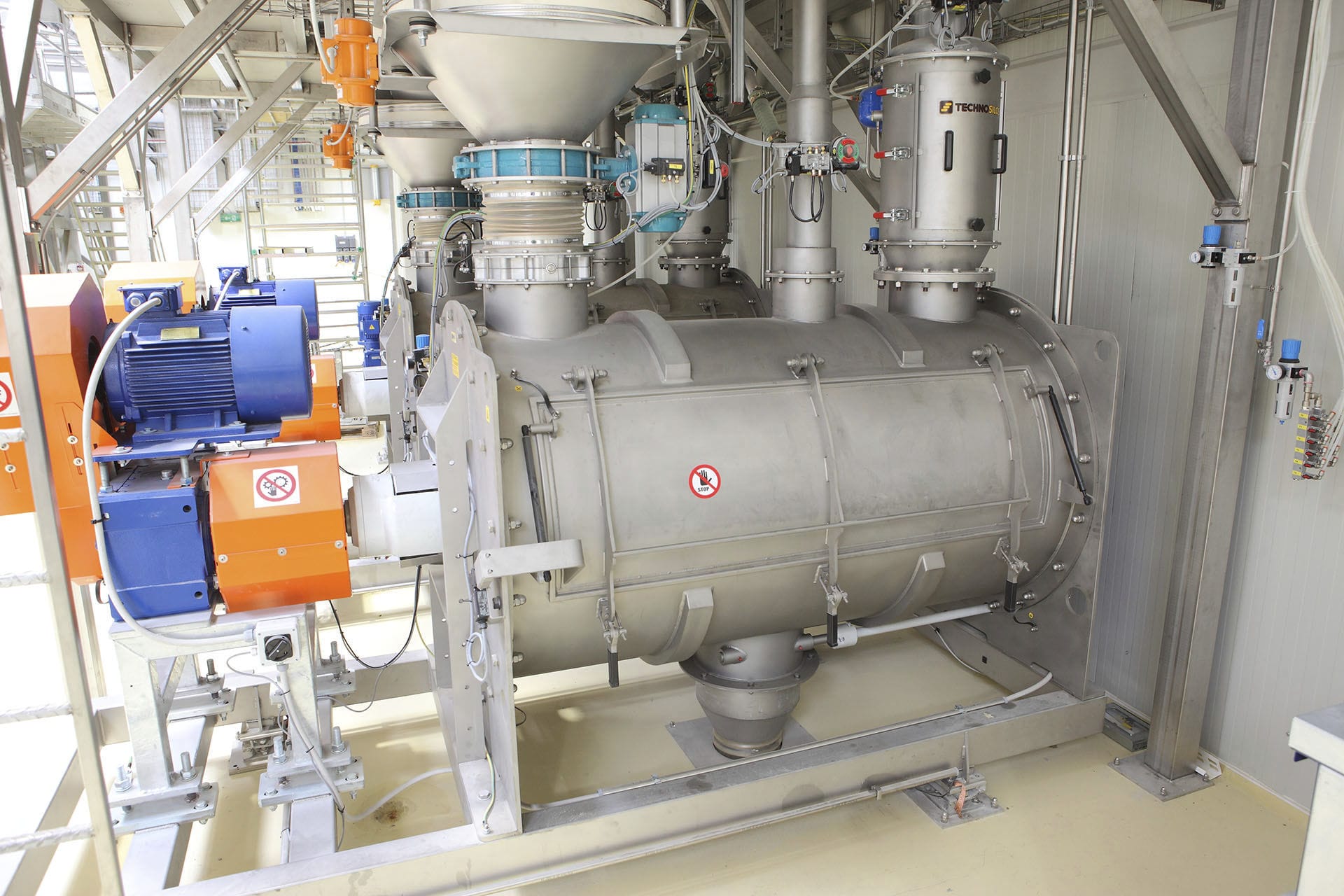
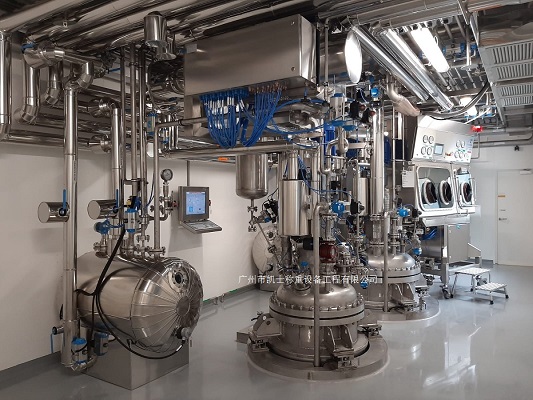
The batching machine mainly consists of three parts: feeding, weighing, and discharging. The feeding part is composed of a spiral conveyor. It sequentially completes the transportation of materials. The weighing part consists of the reaction vessel, four sets of Weighing modules, and the weighing instrument, completing the measurement and quantitative control of various materials. The feeding part consists of a discharging spiral and an air valve for the discharging port. It completes the positioning and feeding of the batching machine through various detection switches. Through the tubular spiral conveyor suspended under the material storage tank, the materials from each material storage tank are successively added to the weighing reaction vessel. When each material is added, the weighing instrument sends a signal to the PLC, which then stops the addition of that material and starts the addition of the next material. The amount of each material added is determined by the preset value in the weighing instrument.
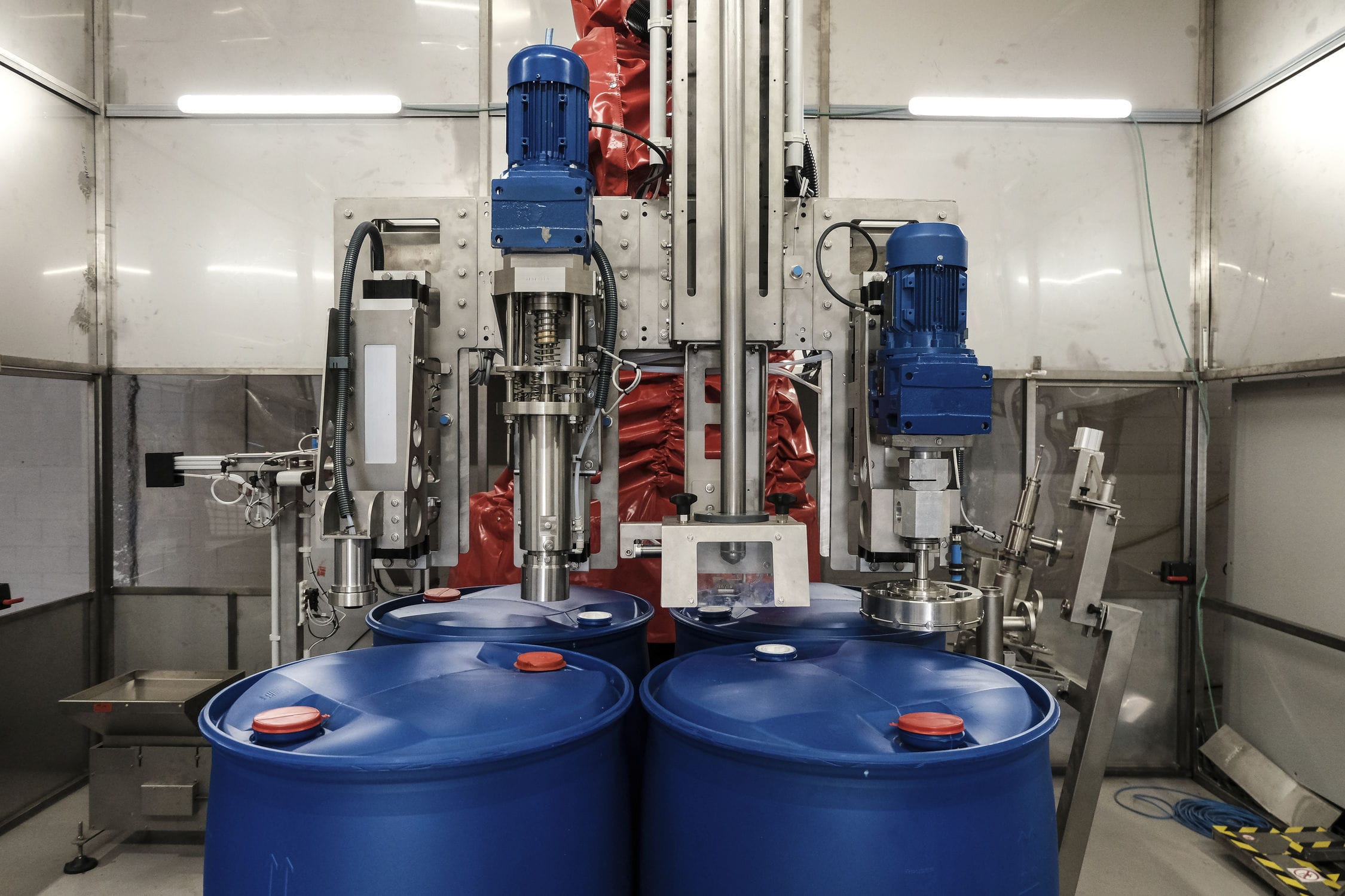
After batching is completed, the pre-bagged materials are placed in the corresponding mixing machine according to the working conditions of the mixing machine. When feeding material to the No. 1 mixing machine, the pneumatic gate on the lower part of the weighing reaction vessel is opened, and the discharging screw of the weighing reaction vessel rotates in reverse, sending the material in the tank out and into the No. 1 mixing machine. When the material is finished being fed, the weighing instrument resets and sends a signal to the PLC, which then stops the rotation of the screw conveyor in the tank and automatically closes the discharging gate plate. Then, batching is repeated. When feeding material to the No. 2 mixing machine, the tubular conveyor below the weighing reaction vessel does not rotate, only the No. 2 gate plate is opened. When the PLC receives the signal to open the No. 2 gate plate, the weighing reaction vessel starts to rotate in the opposite direction, and the material is sent through the tubular conveyor into the No. 2 mixing machine. When feeding material to the No. 3, No. 4, and No. 5 mixing machines, the corresponding gate plates are opened, the tubular conveyor rotates, and when the PLC receives the signal to rotate the tubular conveyor, the material in the weighing reaction vessel starts to rotate, and the material is sent through the tubular conveyor to the discharging port with the opened gate plate, and then falls into the corresponding mixing machine below.
The material supply in the Batching system uses the inlet and outlet spiral. The spiral is driven by a variable frequency motor through a variable frequency converter. The system controls the operating speed and start/stop of the motor based on the current weighing weight and the target weight. When the weighing weight reaches the allowable error of the target weight, the spiral stops feeding. The target weight of weighing can be set through a task call from the upper computer or directly input by the touch screen as the weight. Using a screw motor, the lateral movement is achieved separately, enabling the ingredients to be added into the reaction vessel. The screw motion realizes the control of the feeding process. The entire operation process starts from the initial point, where a weighing module is installed at the bottom of the reaction vessel. Firstly, the amount of ingredients in the silo is detected, and at the same time, the height of the liquid level in the reaction vessel is detected. When there is enough ingredients in the silo but the liquid level in the reaction vessel is low, the screw feeder starts, and the lateral movement begins. The motor reaches the end point of the lateral movement, and then the screw motor starts to feed the ingredients to the feed inlet of the reaction vessel. The height of the liquid level in the reaction vessel is detected. The input voltage is adjusted by a variable resistor, and the input signal is compared with the feedback signal from the weighing module to form a control signal. After PID regulation and power amplification, the proportional valve realizes the drive and control. The motor speed is achieved in a closed-loop control.
The screw conveyor and gate valve cylinder drive, and the screw feeder and gate valve cylinder drive system use variable-frequency motors for feeding. The maximum pressure of the system is adjusted by a safety valve. The flow direction of the hydraulic material is controlled by an electromagnetic directional valve, achieving the forward and reverse rotation of the hydraulic motor and the opening and closing of the gate valve cylinder. The gate valve cylinder is internally equipped with a displacement sensor to achieve precise position control of the gate valve. The drive system also uses a proportional variable-frequency motor for feeding, and two pilot relief valves on the two-way cartridge valve block set two system material pressures. The forward and reverse electromagnetic directional valves are realized. Both variable-frequency motors are priority for constant power control and quantitative control. If the set flow or working pressure exceeds the power curve, constant power control replaces the electronic variable-frequency control and reduces the displacement according to the constant power curve. When below the power curve, the displacement is adjusted by the control current. The motor output flow is only related to the input control signal and is not affected by the load pressure change. The drive motor realizes overpressure protection through two built-in relief valves. The inlet and outlet of the motor are connected to the two-way valve blocks at both ends, and the inlet weight of the weighing module is detected as the control signal and fed back to the controller.
The batching system consists of PLC, weighing instruments and buttons. This system has two control modes: automatic and manual. It includes manual feeding signal, manual discharging signal, manual and automatic selection signals for feeding and discharging, whether the batching machine is running or not, various material weighing signals and reset signals of the weighing instrument. The over-limit signal of the reaction vessel liquid level, the signal of whether the screw conveyor is rotating, the opening and closing check signal of the discharging gate plate, the manual discharging signal, the check signal of the valve closure, the closing signal of the batching machine discharge door, the signal required by the operator for adding materials in the next batching machine, and the reversing valve signal. The main PLC output signals are used to control the starting and stopping of the feeding screw, discharging screw, discharging reversing valve, feeding reversing valve, and discharging reversing valve and other equipment, as well as the pressure and material level alarms.


