


The structural layout of the hopper scale is as follows: grab → hopper scale → feeding hopper → feeding belt conveyor → electric three-way → wharf belt conveyor. It is composed of a hopper scale, an electro-hydraulic arc-shaped gate, a weighing module, a threshold type support steel structure, etc. The hopper scale is not firmly fixed on the steel structure of the ship unloader, but a set of sill support steel structure is designed for this hopper scale. The frame-supported steel structure is composed of the support beam of the hopper scale, the door legs on the river side and the door legs on the land side of the pulley, as well as the connecting reinforcement beam.

 020-34563445
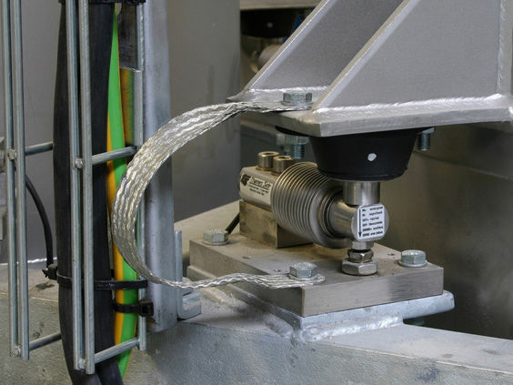
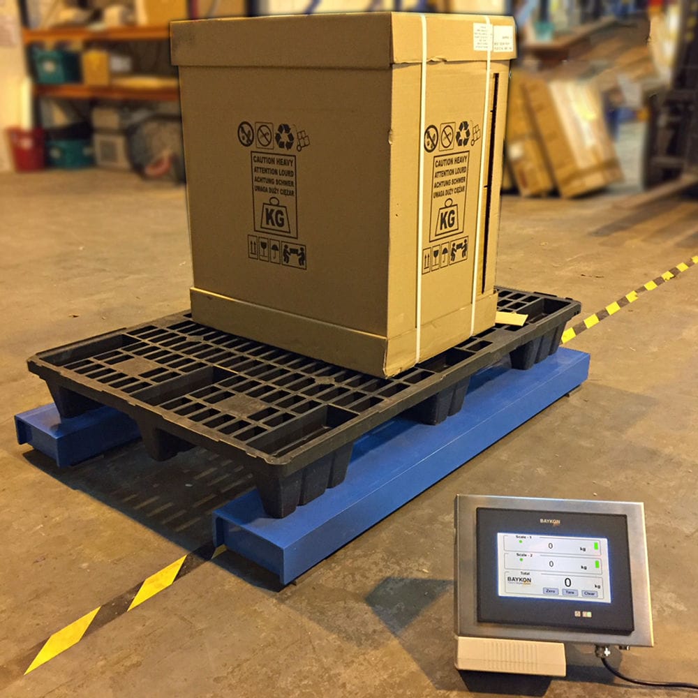
The hopper Weighing system is composed of weighing hoppers, Weighing modules, calibration weights, arc doors, receiving hoppers and feeding equipment. Under the condition of keeping the equipment static, the weighing module of the weighing hopper is calibrated with weights. The equipment starts to pick up materials, only picking up 2 buckets of materials, and the weighing process is completed in the weighing hopper. Then, open the arc door handle to place the materials into the receiving hopper and transfer them out through the discharge belt conveyor. After all the calibration materials have passed through the belt scale, obtain the data of the belt scale. Therefore, the data from the hopper weighing can be used to calibrate the belt scale.
This weighing system is composed of a hopper scale, an electro-hydraulic arc-shaped gate, a weighing module, a threshold type support steel structure, etc. The hopper scale is not firmly fixed on the steel structure of the ship unloader, but a set of sill support steel structure is designed for this hopper scale. The frame-supported steel structure is composed of the support beam of the hopper scale, the door legs on the river side and the door legs on the land side of the pulley, as well as the connecting reinforcement beam. The legs of the river and land sides of the carrier-carrying wheels respectively pass through the river and land side crossbeams of the ship unloader and are directly supported on the dock tracks. The support beam frame is set on the legs of the river and land side doors, and the hopper scale is erected on the support beam through four sets of pin-type weighing modules. The entire set of threshold type support steel structure is suspended from the body of the ship unloader without interfering with each other, and is only connected to the ship unloader through electric pins. When the main vehicle of the ship unloader is moving, the hopper scale system is connected to the ship unloader by an electric pin and moves synchronously with the ship unloader through the outrigger wheels. When the ship unloader stops moving and the grab starts to pick up materials, the electric latch automatically disengages and becomes independent of the ship unloader. At this time, the weighing system is based solely on the quay track and directly transmitted to the quay tracks on both the river and land sides, unaffected by the overall shaking and impact of the ship unloader during operation, and they do not interfere with each other. At this point, weighing and measurement are carried out, thus achieving static measurement. The interconnection of the entire set of support steel structure door legs and load-bearing beams adopts flange connection form, which is convenient for the rapid installation and disassembly of the structure.
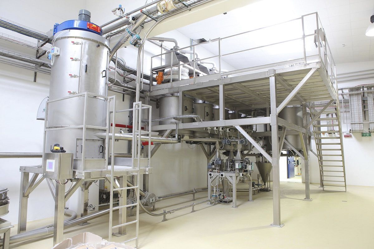
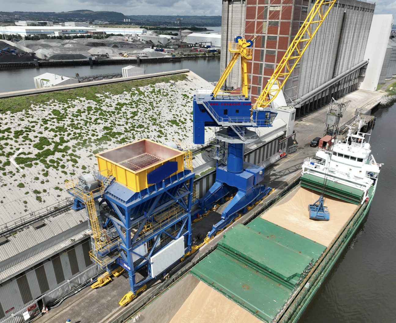
When operating a ship unloader, static weighing and measurement of materials are carried out, using the method of hopper weighing and measurement. Two layers of hoppers are set on the ship unloader, with the upper part being a smaller hopper scale (which has an independent steel structure support system and is independent of the ship unloader body without interfering with each other). The support part of the bucket body is equipped with multiple high-precision weighing modules, and the lower part is a larger feeding bucket. The structural layout of this static weighing system is as follows: grab → bucket scale → feeding bucket → feeding belt conveyor → electric three-way → wharf belt conveyor.
After the material is grabbed in this scheme, when the grab moves above the hopper scale, the material is placed in the metering lake. After the impact stabilizes, the weighing module weighs out the mass of the material grabbed in the hopper scale. Then, the hopper scale gate opens and closes, and the weighing module weighs out the mass of the remaining material in the hopper scale. The mass of the material placed in the feeding hopper is then determined. The total time for one material weighing (waiting time + weighing time + time for opening and closing the gate) should be less than the time of one working cycle of the grab. Wait for the next working cycle when the grab grabs the material for the second weighing to obtain the mass of the material placed in the feeding hopper for the second time. If the ship unloader works continuously and the above process is repeated, the total mass of the material grabbed by the grab can be measured. When 2 to 3 hoppers of materials fall into the feeding hopper, the electro-hydraulic gate under the feeding hopper begins to open, and the feeding belt conveyor continuously and evenly feeds the elevated belt conveyor at the wharf.


