
 2020.02.10
Summary:The hopper scale batching machine inputs the weight of the ingredients through the industrial computer, generates the weights of various materials according to the ratio of raw materials, and transmits them to the PLC through communication.During the batching process, dynamic real-time monitoring is carried out, the detection and other switch values in the control system sent from each slave machine are regularly collected, the weight signal of each material is collected in real time and compared with the given signal to determine the next control plan, and at the same time, The weight signal is sent to the host computer.
0 Preface
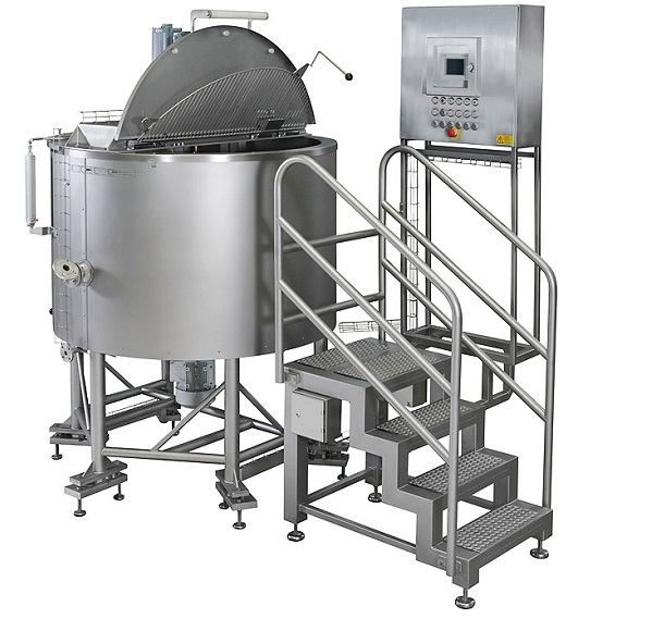
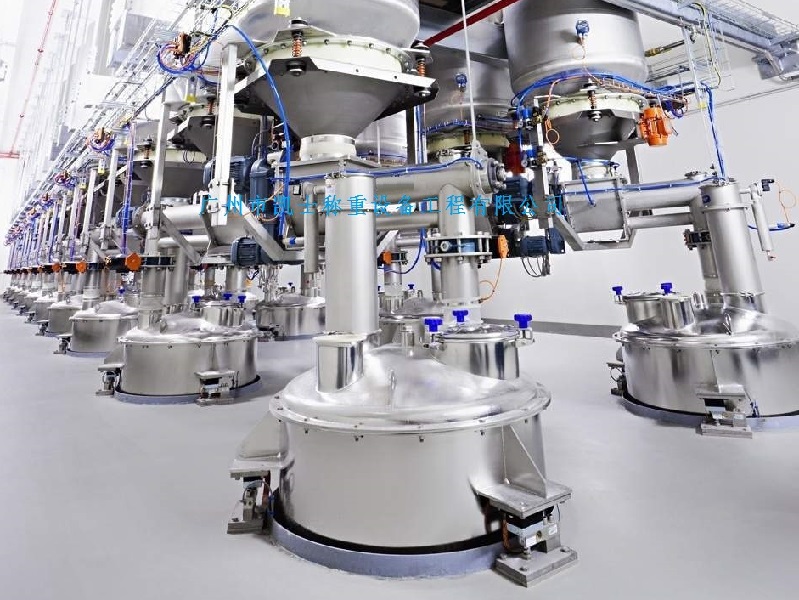
Hopper scale as a material dosage measurement and control equipment, in the south of the small and medium-sized cement plant has a wide range of applications. This is a whole fixed in a weighing module, the bottom of the side of the installation of a solenoid pneumatic valve can be opened and closed by the bucket door for timing, quantitative unloading and feeding (when the bucket door is open when the hopper scale material is unloaded, and when the bucket door is closed when the material can be through the electric vibration machine or the spiral more knife from the top into the hopper scale) by the hopper weigher composed of metering and dosage equipment. Due to the hopper scale has a simple structure, easy to produce, low failure rate, batching accuracy to meet the requirements of the cement production process and widely used in small and medium-sized cement plants.
1 technical requirements for hopper scale batching machine improvement
For the new hopper scale batching machine, Hushan Company puts forward the following technical requirements:
(1) The batching machine contains a total of 20 hopper scales, including 4 sets of clinker scales, 2 sets of gypsum scales, 3 sets of stone scales, 1 set of furnace bottom slag scales, 10 sets of fly ash scales and so on. These 20 sets of scales are numbered as "1~#20 hopper scales and their feeding methods are: clinker scales, gypsum scales, stone scales, furnace bottom slag scales, etc. are fed by electric vibration machine, and fly ash scales are fed by spiral knife. The batching machine is required to be able to control the feeding amount of these 20 units by controlling the starting and stopping of electric vibration machine or spiral knife (hereinafter referred to as feeding equipment).
(2) The mill operator can select any of the 20 scales to participate in the dosage according to the needs of the operator interface, and can be switched automatically or manually on the operator interface: enter the automatic state when all the scales selected into the fully automatic dosage state, according to the given total flow and the ratio of each scale week after week for feeding and unloading, comparing the net weight of the material entering the scale with the target value and the formation of the next scale, the target value of the material, and the dosage of the material, and the dosage of the material, and the dosage of the material. It compares the net weight of the material entering the scale with the target value and forms the target value for the next scale, and totalizes the net weight of the material. When entering the manual state, the mill operator can manually start and stop the feeding equipment, open and close the bucket door of the hopper scale, and can calibrate the hopper scale and correct the corresponding parameters.
(3) When the system enters the automatic state, the N synchronized units selected to participate in the dosage will do feeding and unloading only once in a time period of 16s for each dosage cycle (to~ti=2.5s, close the hopper door; ti~t=9s, feed time; t~t~t=1s, stop feeding and wait for the time period; t4~ts~te=3.5s, open the hopper door). Close the unloading bucket door and start feeding equipment feeding, when the unloading time reaches or the net weight of the material entering the scale body is close to the target value, considering the inertia of the material exists should be stopped in advance of the feeding equipment. Elected to participate in the dosage of N scales all complete a dosage cycle, the N scales at the same time into the next dosage process, and so on.
(4)When the system enters into automatic state, the control mode of each scale is as follows: close the bucket door of the scale by closing the electromagnetic pneumatic valve, start the feeding equipment after a certain time delay, and the materials will be fed into the scale; when the net weight of the materials in the scale is close to the target value or when the materials have been fed for 9s, the feeding equipment will be stopped, and the bucket door will be opened to unload the materials by starting the electromagnetic pneumatic valve after a time period of static position.
(5) In a dosage cycle, if a certain scale or several scales do not feed or do not feed enough, then alarm, and the next dosage cycle for replenishment; if a certain scale tare is too large (such as more than 20kg), then alarm and stop the scale; if a certain scale does not have enough material for three consecutive times, then stop feeding the scale and alarm. In a dosage cycle if a scale has too much material, it will reduce the material in the next dosage cycle.
(6) Each scale is weighed once for every 24 scales for 16s, and the average of the sampled tare values obtained in this 16s time period is taken, and this value is used as the tare weight in the next 24 dosage cycles.
(7) Configure the production report on the operation interface: the content of the report includes the duty time of each shift, the number of dosage scales of hopper scales for all the materials passing through, the number of alarms, the waiting time for the alarms, the shift, monthly and yearly outputs of the 32.5 grade and 42.5 grade cements, the hourly outputs of the grinding mills, the proportion of each kind of materials and the actual dosage, the data of the laboratory inputted through the keypad, and the printing of the report.
(8) The need for future system expansion must be considered.
2 hopper scale dosage machine transformation of the overall program
As the hopper scale batching is a scale by scale, hopper scale batching system obviously belongs to the so-called "intermittent" batching system which is different from the current popular "continuous" batching system such as belt scales or rotor quantitative feeder, and this "intermittent" batching system is completely non-standard. The hopper scales in the "intermittent" batching system are completely non-standard scales, with poor working conditions on site, difficulty in realizing precise control, and greater difficulty in system design. According to the above technical requirements, the following solution is proposed: the hopper scale mixer adopts the form of Siemens S7300 PLC on-site control station + host computer to form a DCS control system, in order to realize the dosage control of "1 mill. That is, the hardware part of the field control station adopts Siemens S7300 series module, and the software of the operation station adopts WinCCV6.2 version. Its controller program contains the following aspects.
(1) Analog input program block and digital filtering function block to complete the weight signal processing of 20 sets of secret.
(2) Measurement control program block, which is the main control program, all 20 scales of the feeding method, feeding equipment start and stop, the opening and closing of the bucket door, a variety of alarms, the next scale of the target value of the calculation of the weight value of the current sampling of materials such as cumulative value of the program are processed in this block; because when the ratio of each scale is given after the control of the relative independence of its control, and the control of each scale are the same, so it can be compiled to apply to the weight of the scale. Since the control of each scale is relatively independent after the ratio is given, and the control of each scale is the same, the function block applicable to the control of each scale can be programmed.
(3) Dosage setting program block, the target value of each scale of each scale is given by the calculation of the total given flow rate and the ratio of the scale.
(4) Weight totalization program block, the weight of each - scale of all scales involved in dosage, the flow rate of each scale, the actual total flow rate divided into 32.5 grade and 42.5 grade cement varieties are calculated in this block.
(5) Total zeroing program block, each shift report, monthly report, annual report after printing to print the data before zeroing.
(6) Year, month, and day time calculation block, year, month, and day time related to the report, conversion of day, middle, and night shifts, and the time needed to calculate the flow rate.
The configuration of the main operating interface of the upper computer mainly accomplishes the following functions: inputting the proportion of each unit, the target value of the moment, the target value of the next scale, the average tare, the current tare, the current net weight, the totalization of the weight of a single scale, the actual proportion, manually opening and closing the hopper door, manually starting and stopping the manual/automatic control of feeding equipment to switch the total flow rate of the 32.5-grade and 42.5-grade cement to the given, the feedback of flow rate, and the total accumulation of the total weight, etc. The total flow rate of each unit can be set, the flow rate feedback and the total accumulation of weight, and other variables. For the production daily report, the ratio of each scale, the actual blending amount, monthly material weight accumulation, annual material weight accumulation, weighing times, alarm times, alarm waiting time, mill hourly output, cement production, cement shift production, monthly cement production, annual cement production, hourly cement fineness value, SO; content, storage space and other variables can be configured to the production daily report. Also need to configure the alarm interface and calibration scale interface and so on.
3 bucket batching machine PLC hardware control circuit design
This system involves the control circuit is mainly PLC hardware control circuit, the design program is as follows.
(1) The power supply voltage of controller CPU315-2DP is DC24V, which is supplied through power module PS307.
(2) switching input module SM321/16DI, the system has two switching input module SM321/16DI, its power supply voltage is AC220V, of which KB1 ~ KB20, etc. were "1 ~" 20 scales bucket door closing status feedback signal. Bucket door closure is the corresponding KB contact closure, and vice versa, the contact breaks, switching input module can be tested in real time to the KB contact closure and breakage status.
(3) switching output module SM322/32D0 and SM322/16DO output signal circuit, where the power supply voltage of the two modules are AC220V. KA1 ~ KA20, etc. are respectively "1 ~" 20 dosage equipment start-stop drive relay, KA21 ~ KA40 are respectively "1 ~" 20 scales of the bucket door open and close the drive relay. When the drive relays KA1~KA40 are energized, the corresponding drive signals are output to drive the corresponding equipment.
(4) analog input module SM331/AI8 (a total of 3 blocks in the system), analog input module SM331/AI8 power supply voltage is DC24V, which corresponds to the analog channels with the terminals 601 ~ 603, 605 ~ 607, --... --, etc. are connected to the output signal terminals of the weighing module of the 1~"20 scale, the output signal of the metering module ranges from 0~10mA, and the channel parameter settings of the analog input module SM331/AI8 need to be matched with it. So that the weight signal of the material in the scale can be sampled through the corresponding analog channel.
4 Software Programming of the Hopper Scale Batching Machine
The following is a detailed description of the structure and program functions of several major PLC programs of the hopper scale batching machine.
(1) Analog input program block. This is the weight of each scale input signal processing, converted to real numbers and then such n real numbers and then take the average of the program. The weight signal of each scale is fed into the analog channel of the PLC, and the analog channel converts the signal into a digital signal that can be processed by the PLC CPU. Under normal circumstances, the analog input module will be a variety of analog input signals are indiscriminate uniformly converted to 0 ~ 27648 between the physical meaning of the pure digital quantities, and then by the A/D conversion to obtain the actual physical meaning of the data. Conversion must take into account the corresponding digital quantities corresponding to the measurement of a physical amount of instrumentation unit of measurement and its range. For example, for a scale of a weight signal G by the PLC's analog input channel after conversion into a digital quantity M, and then converted into a floating-point number N, according to a simple proportionality relationship can be obtained G.N/27648xhxHIRANGE (kg) (for clinker scales, HIRANGE = 300; for other scales, HIRANGE = 150, h is the correction factor for calibration), that is, the calibration of scales when the correction factor), that is, after this operation can be purely digital quantity N into real numbers for the CPU to deal with.
(2) Measurement control program block. This is the main program in the dosage system, including the start-stop program of the feeding equipment, the opening and closing program of the hopper door, various alarm programs, replenishment and material reduction (i.e., when the weight of the material into the hopper scale is less than the given weight, then increase the amount of material for the next scale, and vice versa to reduce the amount of material for the next scale, which is actually an "intermittent" negative feedback control). This is actually a kind of "intermittent" negative feedback control (conditions and methods), weight accumulation of a single unit in 32.5 and 42.5 levels, and so on. The automatic time-cycle control program for each scale consists of 6 delay timers (T~T...s), which constitute a time-cycle control program through the cyclic start-up of the previous timer to start the next timer, and the last timer to activate the first timer to enter a new cycle. When the ratio of the selected scales to be involved in batching is 100%, and the ratio of each of the selected cement varieties (32.5 grade or 42.5 grade cement) is not zero and there is no shutdown alarm, and the system selects automatic operation, each hopper scale involved in batching will automatically run in a cyclic manner as stipulated in the control program until the stop button is clicked.
(3) Dosage feed program block. This is the interface of 32.5 grade cement or 42.5 grade cement given the total flow and each hopper scale involved in the dosage of the given ratio to calculate the single dosage target value of each scale, each after 24 times of dosage and then the previous since the shift operation (or each shutdown) since the cumulative amount of the target value of the accumulated amount of the cumulative value of the feedback (cumulative deviation) is evenly distributed to the next 24 times the dosage of target values, to form the next 24 times the reference value of the reference value of the scale, the next 24 times. A reference target value for the next 24 scales is formed, and the amount of material to be discharged at each of the next 24 scales of each hopper scale involved in the dosage is essentially determined thereby. The method of forming the reference target value by calculating the target value is actually the so-called negative feedback closed-loop control in "intermittent" dosage control, which can really realize the improvement of the average dosage accuracy and dosage stability of the dosage process.
(4) Weight accumulation program block. It is used to add up the respective accumulated weights of each hopper scale involved in dosage into 32.5 grade and 425 grade varieties, calculate the corresponding total output of 32.5 grade and 42.5 grade cement in the current shift, and calculate the hourly output and the hourly output of each scale according to the total output of the current shift and the running time.
(5) Total clearing program block. This is the program that the duty clerk will automatically clear the total weight of each scale, the number of dosage, the total output of 32.5 grade and 42.5 grade cement, and the number of total alarms of the current shift while printing the report when the duty clerk is on duty for the full 8h shift. If the printing coincides with the 24th of the month, the accumulated monthly weights of all scales of the month and the corresponding monthly output of 32.5 grade and 42.5 grade cement will be cleared to zero at the same time; if the printing is done on December 31st, the accumulated annual weights of all scales of the year and the corresponding annual output of 32.5 grade and 42.5 grade cement will be cleared to zero at the same time.
(6) year, month, day time calculation and display program block: the program block by calling SFC1, FC6 and FC8 and other system functions, with the help of FC6 to SFC1 to read the DT format "DateAndTime" parameter into a "Date (i.e., day)" as the unit of double byte. "as the unit of double-byte decimal number, and then through the "Date" parameter calculation to obtain the "year", "month", "day" and so on. "Day" and other units of time parameters; with the help of FC8 to SFC1 to read the DT format "DateAndTime" parameter into a "TOD (i.e., milliseconds) "as the unit of double-letter decimal number, and then through the "TOD" parameter calculation to obtain the "hour", "minute", "second" and so on. "seconds" and other units of time parameters. These time parameters are mainly used in production reports for "year", "month", "day" and "hour", "minute", "second" and so on. These time parameters are mainly used for the display of "month", "day" and "hour", "minute", "second" and other time parameters in the production report, the calculation of the output of the report, the printing of the report when the monthly output and annual output of the timed zero, the day shift, the middle shift, the night shift and other shifts such as cyclic display of the parameters.
5 Hopper scale batching machine operation interface configuration
Hopper weigher operator interface configuration, first of all, to meet the hopper weigher batching system control requirements, while providing operators with user-friendly interface to better achieve effective control of production. According to the need, we have configured the operation interface of the hopper scale automatic dosage system with five screens, namely: "1 Cement mill dosage system operation screen, alarm screen, parameter correction screen, production daily report printing screen, production query screen, etc. These screens are configured with all the operation buttons required for the operation process (used to operate the equipment, switching or opening the screen), the dynamic display objects and the input/output fields for the operator to operate the equipment and the output/output fields for the operator to operate the equipment and the output/output fields. These screens are configured with all the operation buttons (for operating the equipment, switching or opening the screen), dynamic display objects and input/output fields for the operator to operate the equipment and monitor the various states of the equipment.
6 Installation and commissioning of the hopper scale batching plant
6.1 Installation of the hopper scale batching plant
Hopper scale batching machine installation work is relatively simple to complete, including a variety of power lines, control. Signal line connection, set up various parameters of the system, communication connection program download and other work. And then activate the WinCC project of the head weigher batching machine configured on the host computer, the operator can realize man-machine dialogue with the CPU of the field station through the host computer, so as to realize the control of the field equipment.
6.2 Commissioning of hopper scale batching machine
The debugging of hopper scale batching machine includes: weight calibration of each scale, bucket door opening and closing test, starting and stopping test of feeding equipment, automatic cycling test of a single scale, adjustment of "feeding quantity control coefficient" of each scale, and adjustment of alarm parameters of each scale.
(1) Weight calibration of hopper scale. Firstly, open the parameter correction screen, then place 5kg/only weights on the scale to be calibrated, and compare the weight increase value of the "symbolic scale" corresponding to the scale on the parameter correction screen with the total weight of the added weights, and if there is a deviation between the two, then "amplitude correction parameter" is adjusted for the hopper scales in the screen, until the "feed quantity control factor" is adjusted for each scale, and the alarm parameters of each scale are adjusted. If there is a deviation between the two, the "amplitude correction parameter" of the hopper scale in the screen will be adjusted until the deviation between the two reaches the required range.
(2) Bucket door opening and closing test. Open "#1 cement mill batching system operation screen", click on the screen configuration in the control of a scale bucket door open, close the "symbol button", observe and the hopper scales corresponding to the bucket door should produce the corresponding action; if the bucket door does not move to do or action error, may be a problem with the operation screen configuration, may also be a PLC program error, find the reason and correct it. May be a problem with the configuration of the operating screen, may also be a PLC program error, find the cause and correct.
(3) start-stop test of feeding equipment. Methods and bucket door open and close the test method is exactly the same, will not repeat here.
(4) single scale automatic cycle test. Input a given total flow and need to test a scale of the ratio of the given value, so that the scale of the target value of the size of the permissible range; and then click on the automatic/manual conversion button to make the scale into automatic operation, observe the scale of each automatic cycle cycle of the length of time is strictly in line with the specified time, and in the time period with the scale of the bucket door and the action of the feeding equipment is in the program (c) The operation of the hopper doors and feeding equipment associated with the scale at each time period occurs under the specified conditions.
(5) Adjustment of the "feed volume control factor" of the scale. Since the downward opening of the feeding equipment of each scale is at a certain distance from the bottom of the scale or the material accumulation layer, the weight of the material can be weighed by the weighing module only when the material falls to the bottom of the scale or the material accumulated in the scale. The feeding equipment is stopped when the feedback weight of the weighing module is equal to the corrected daily scale value, so there is still a part of the falling material that is not weighed at the moment of stopping the feeding equipment. When this part of the material is all down, the weight of the material in the scale will definitely exceed the corrected target value. In order to make the hopper scale in the dosage of each time the amount of material and the correction of the target value as close as possible, then the feed equipment must be in the scale of the material weight of the feedback value is close to, but not yet reached the correction of the daily standard value of the early shutdown. We therefore control the corrected target value by multiplying it by a factor of less than one (the "feed volume control factor"). We can repeatedly adjust the "feed quantity control coefficient" of each scale to make the dosage quantity of each scale as close as possible to the corrected target value, so as to improve the dosage accuracy of each scale.
(6) Adjustment of alarm parameters. The hopper scale batching machine is equipped with tare alarm, broken material alarm and material feedback weight is less than the corrected weight and deviation over a certain proportion of the alarm, etc. These alarm parameters must be adjusted repeatedly according to the frequency of the alarm in the actual operation process to achieve the purpose of protecting the scale and ensuring the normal dosage.
7 hopper scale dosage machine operation
Since the dosage machine has been used since June 2010, the system has been able to fully meet the requirements of the operational performance; the system is running satisfactorily, especially the dosage accuracy and stability of the system have reached the requirements of the laboratory of the Hushan Company, and the long-term dosage deviation of each shift can be stabilized at 1.0% or less. After the transformation of the batching machine, the 3d strength and 28d strength of each kind of cement produced are very stable, and all the performance indexes have reached the national standard.


