2020.02.09


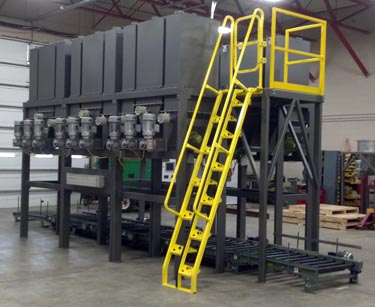
Summary:The mixer ensures the accuracy and reliability of weighing during the mixing process, as well as the accuracy and real-time measurement of the temperature required to fully mix the raw materials.It adopts general computer control and uses PLC to realize mixing control. It has a friendly human-machine interface and is easy to operate.
1 system principle
The mixer control process mainly includes feeding weighing, high mixing tank mixing, cold mixing tank cooling and other three parts.
Press cycleon (cycle start) button, start feeding, feeding motor start, PLC start timer through the negative pressure will be sucked into the hopper scales, weighing raw materials and transferred to the hopper, to be timed to time, PLC gives a control signal, close the feeding motor, open the hopper scales of the discharge port, the raw materials will be sent to the high-mixing tank, at this time, high-mixing motor start. Raw materials in the high mixing tank through the stirring temperature, until it reaches the purpose of mixing (synthesis). In the process of mixing thermocouples will be detected in real time high mixing tank temperature signal value, through the internal A/D converter converted to digital signals, transmitted to the PLC. when the high mixing tank set temperature, PLC sends out a control signal, open the high mixing tank discharge port, the high temperature after the chemical combination of materials into the cold mixing tank. At this time, under the action of PLC control signal, cold mixing motor start, cold mixing pump start water circulation to make the material cooling, thermocouples real-time cold mixing tank temperature signals detected and converted to digital signals, transmitted to the PLC, to reach the set temperature of the cold mixing tank discharge port open, discharge, to complete the process of a mixing.
2 system hardware configuration
In order to realize the control of the dosage machine, a large number of switching and analog input and output signals are required. The system to consider the field signals are: hopper scale in the weighing module to detect the weight signal analog 1 road; buttons, selector switches, limit switches and other switching 19 road, as well as drive solenoid valves, relays, contactors, indicator lights, alarm devices and other switching 21 road.
Switching-based, only a small amount of analog control system, the current commonly used Siemens S7-200 and OMRON COM1 After comparison, the former was chosen because of its strong functionality, cost-effective, and provides a variety of different I / 0 points with the number of CPU modules and digital, analog I / 0 expansion module for users to choose from, the I / 0 terminal rows are easy to remove, easy to grasp, easy to operate. I/0 terminal rows are easy to disassemble, easy to grasp, easy to operate, the specific configuration is as follows:
1) the host for the CPU224 module, a total of 14 inputs integrated I / 0 outputs count 24 digital I / 0 points, can be connected to 7 expansion modules, there is a RS485 communication / programming port, the machine has a 24VDC power supply. System due to the switching points, the use of the local I / 0. Among them, DIO a DI10 (DI11-DI14 Figure 2 is not marked) were accessed buttons, limit switches, manual switches and other switching input signals, and DOO a DO7 (DO8-D09 Figure 2 is not marked) were driven by solenoid valves, relays and other switching output signals.
2) Expansion of an analog input module 6ES54648MC. it has four analog inputs. The mass mV signal detected by the metering module in the hopper scale is amplified to the input range of the module, which is received by the ch.o, and then converted to a digital signal, which is sent to the CPU for control through the system bus.
3) Expand 1 digital input module 6ES54218MA. it has 8 inputs, of which feet 1-2 connect to 24V power supply, and feet 3-10 are connected to the corresponding switching input signals of the cold mixing weighing part. The function of the input module is to convert the level and format of the signals in the field to form the standard signals required by the CPU in the PLC.
4) Expansion of three digital output module 6ES54518MR, which has eight outputs, the output of the common terminal connected to 220V AC voltage, and another 24V DC power supply for this module. The role of the output module is the CPU output standard binary control signals into the production site required to drive the actuator action control signals, such as in this system to drive the corresponding solenoid valve powered action.
5) control panel UNIOP for the LCD laminated keyboard structure, through the PageMode menu selection can be modified online parameters, can also be used as a run-time control, set the real-time clock, manual/automatic conversion, alarms and other functions. When connected to the host computer, the PC/PPL cable can be connected to the PPI interface of the CPU224 module.
The above mixer configuration can complete the whole process of mixing control, the operator only needs to open or close the switch/button in the corresponding position on the panel of the control cabinet, and input the corresponding data through the keyboard, then it can be put into operation.
3 system software design
Programming software Step-7-Mico/WIN specially designed by Siemens for S7-200 series is a 32-bit editing software package based on Windows platform. Its user program structure is simple, the user can use statement table (STL), ladder diagram (LAD) or function block (FBD) three ways of programming, the preparation of the program can be converted to each other, easy to use, easy to learn.
The feeding and weighing process, the mixing process in the high-mixing tank and the cooling process in the cold-mixing tank are called by the main program (monitoring program) as three sub-programs. On this basis, ladder diagrams are generated and edited directly using STEP7 programming software, which facilitates software design and debugging. Such as manual, semi-automatic, automatic mode conversion, the operation of a single valve in manual mode. Adopt the way of running script program behind TARGET (touch screen area) in the flowchart screen to realize human-machine interaction.
3.1 Operation mode switching
To switch from manual or semi-automatic mode to automatic mode, click "AUTO" in the process and operate according to the corresponding prompts.
3.2 Operation of single valve in manual mode
To change the switching state of a single valve in manual mode, click on the icon of the valve in the flow chart screen and operate according to the corresponding prompts.
4 Conclusion
After 2 years of operation of this program, the operator reflects that the human-machine interface is friendly, and prompt information is given when changing the operation, which is easy to operate. Can change the operation mode at any time, set the operation time, the program runs without maintenance, reducing labor intensity, saving money.