


In the granular batching system, when the weighing module detects a shortage of material in the hopper scale, the pump motor starts and operates. The set feeding time and the feeding motor are activated and operate until the weighing module detects that the hopper scale is full of material, at which point all the working motors stop. The batching and discharging process of the system works as follows: when the weighing module detects that the material is in place and determines whether the measurement of the hopper scale by the weighing module reaches the set value, the discharging can be carried out.

 020-34563445
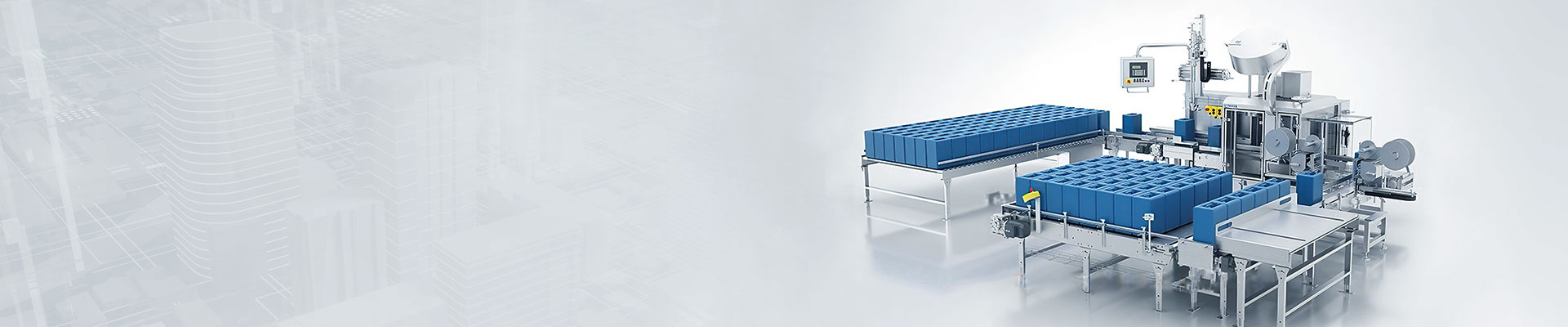
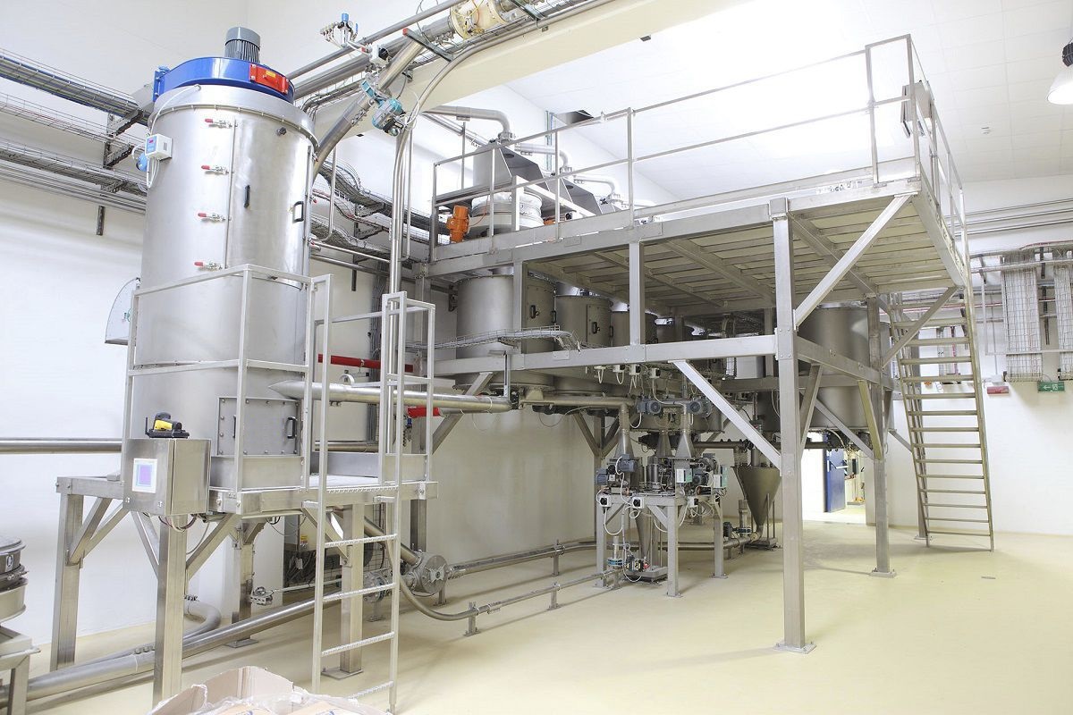
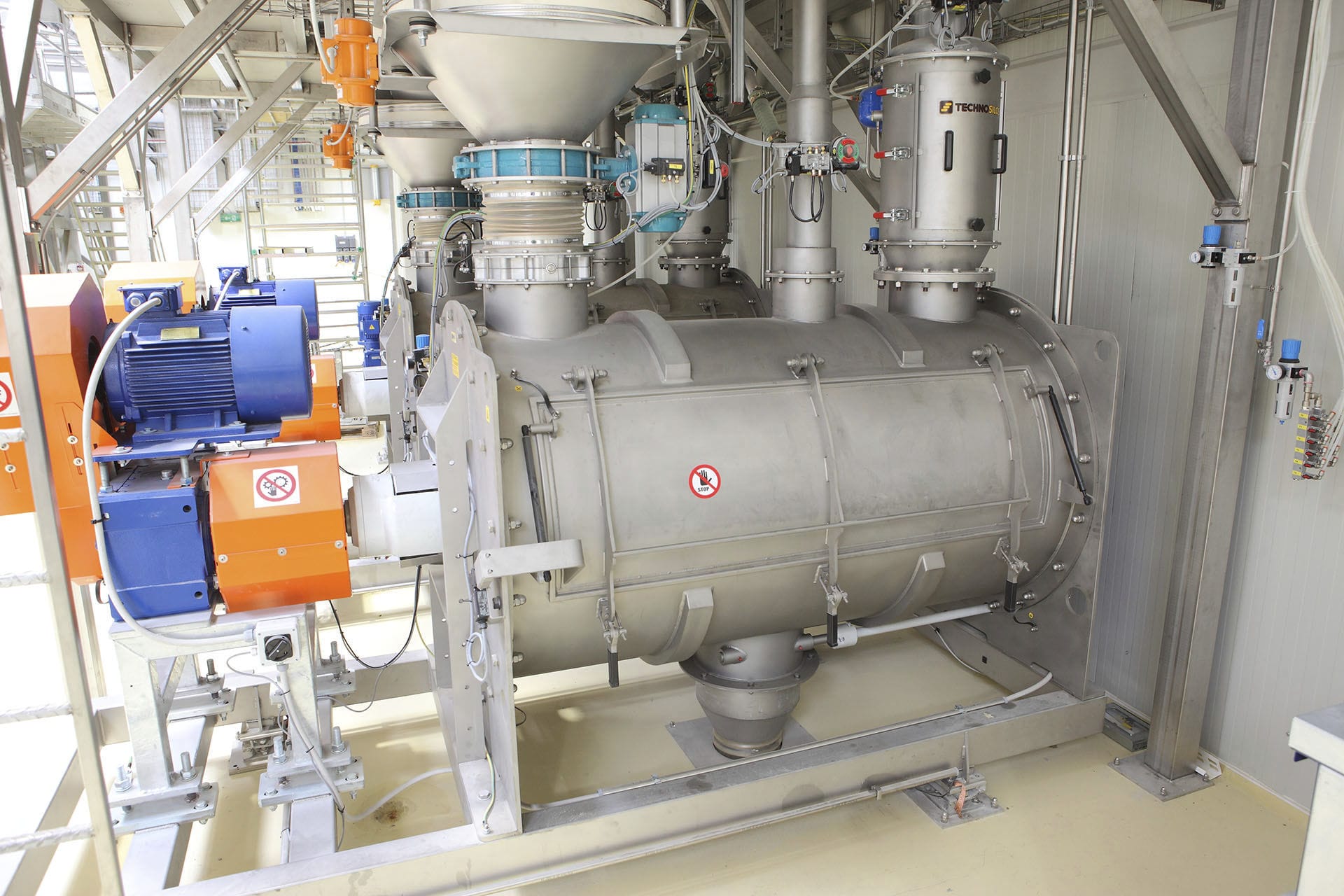
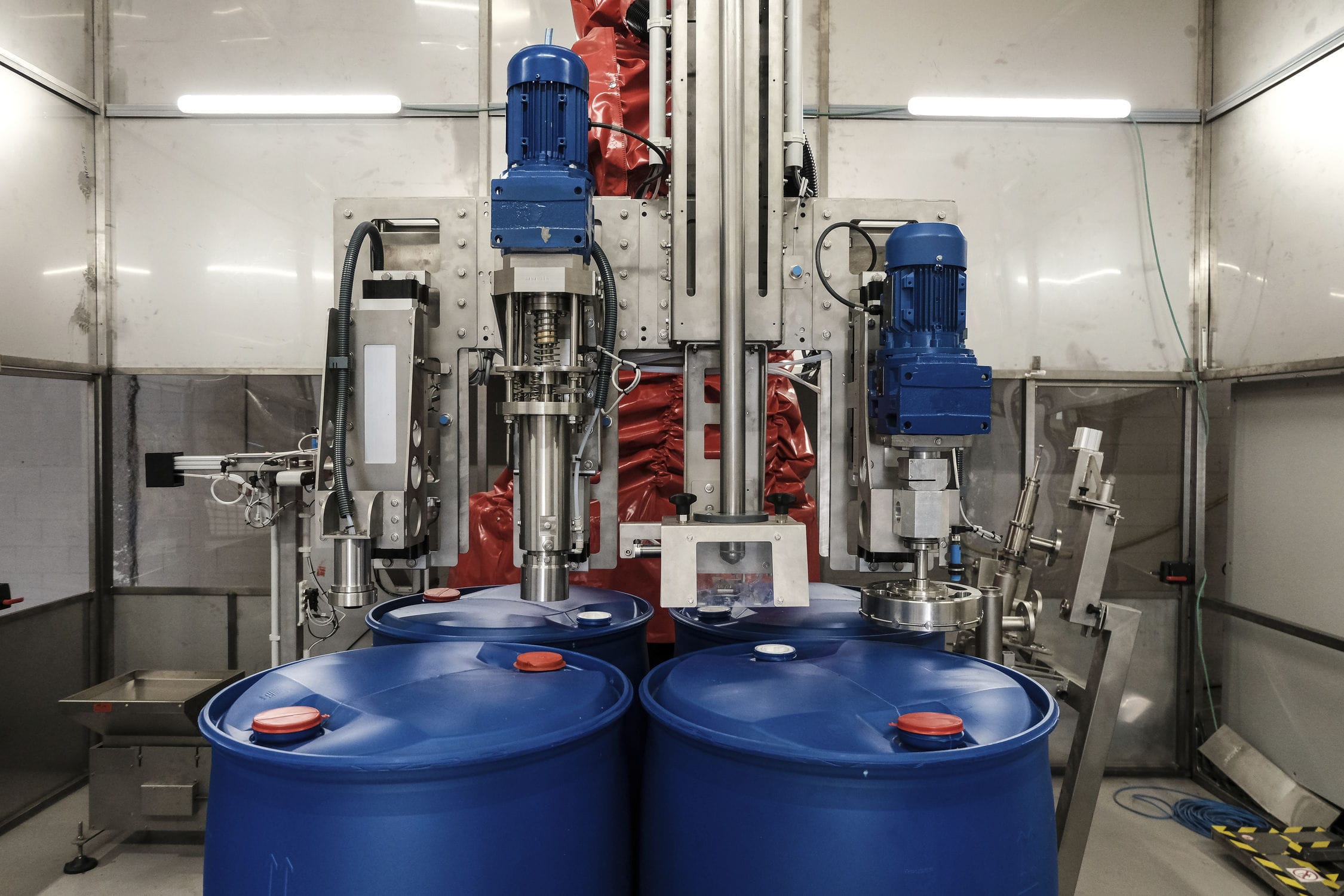
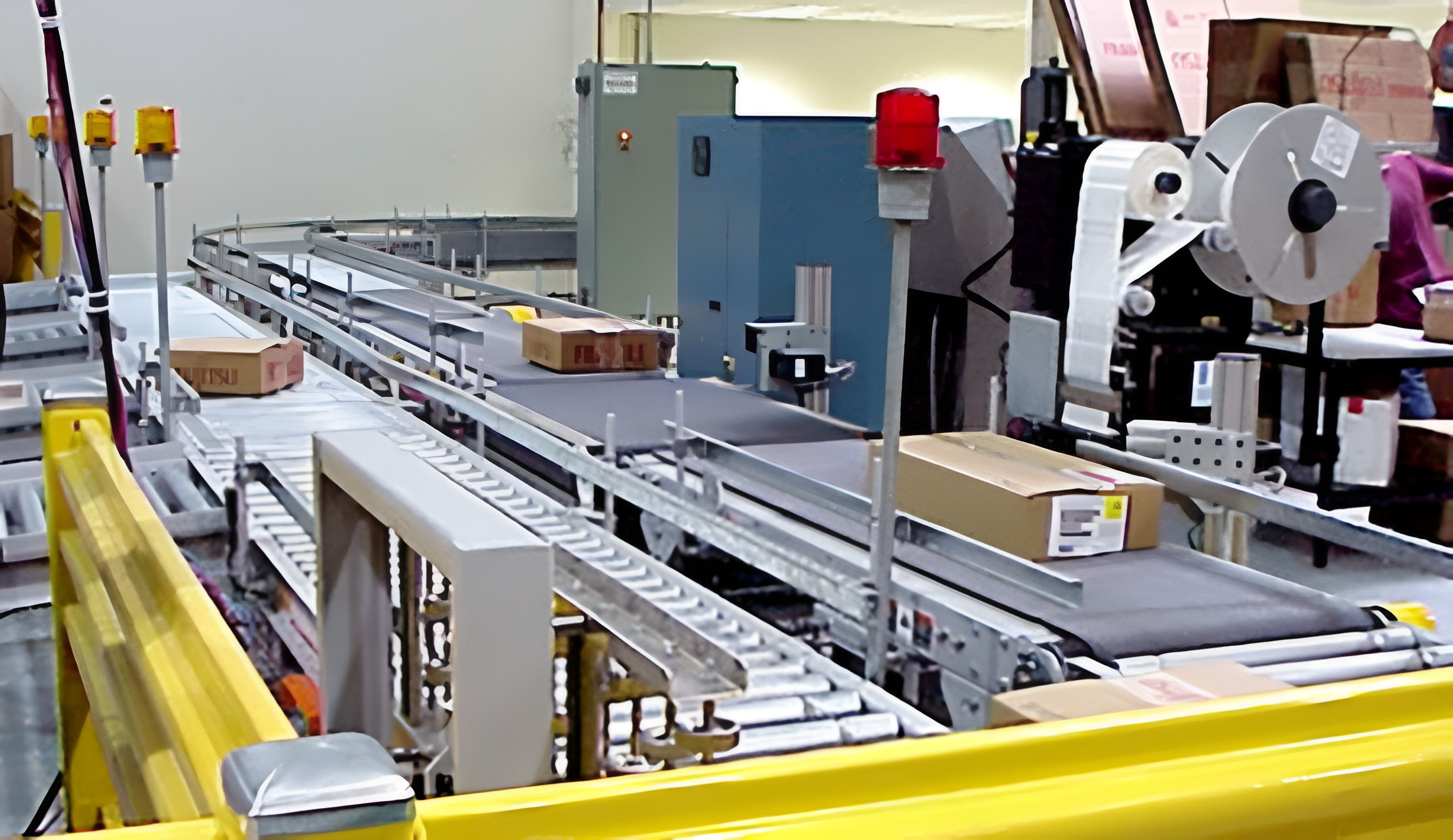
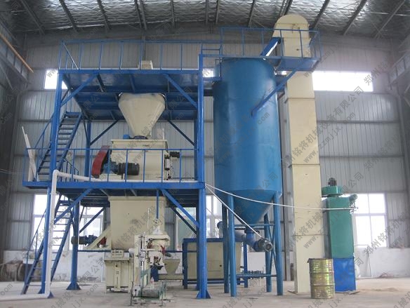
The granular ingredient system includes a weighing module, a hopper scale, a mixer, a conveyor, a metering pump, a mixing tank, an electromagnetic valve, a Filling machine, a one-way valve, and a PLC control system. The pipes are installed under the hopper scale through the electromagnetic valve of the metering pump and the weighing module. The hopper scale is connected to the pipeline via the valve electromagnetic valve and the one-way valve, and the conveyor and the metering pump are connected to the mixing tank. The weighing module, the metering pump, the mixer, the electromagnetic valve, and the filling machine are electrically connected to the PLC control system. The weighing instrument is connected to the PLC control system via the serial port. The PLC control system combines the information stored in the ingredient system to obtain the current ingredient quantity, and then inputs it to the weighing instrument through the serial port interface. The weighing instrument performs comprehensive calculation of the set quantity and the feedback quantity, and outputs the opening degree of the valve controlled by the valve actuator to achieve the purpose of automatic variable ingredient dispensing according to the target quantity and its corresponding ingredient conditions.
When the weighing module detects a shortage of material in the hopper scale of the ingredient system, the pump motor starts and operates. The set feeding time and the feeding motor start and operate until the weighing module detects that the hopper scale is full of material. All the working motors stop only when the weighing module detects that the hopper scale is full of material. During the operation of the ingredient and discharge system, when the weighing module detects that the material is in place and determines whether the measurement of the hopper scale by the weighing module reaches the set value, the material can be discharged. If the measurement of the hopper scale fails to reach the set value, the feeding and ingredient motor starts, the feeding valve opens, the ingredient conveyor starts, and the feeding of the hopper scale continues until the set value is reached before entering the discharge process. If the measurement of the hopper scale reaches the set value, it directly enters the discharge process.
The ingredient system, according to the requirements of the production process, manually or automatically adds multiple materials to one or more hopper scales in a certain weight (or volume) value in a certain Weighing system. The ingredient system is controlled, monitored, and managed by the PLC control system. The on-site control information is connected to the PLC control system through the bus communication method. The PLC control system records and prints various parameters such as the types, quality, and frequency of the various materials. The weighing system is composed of multiple online quantitative ingredient hopper scales and is a centralized control and management system. It adopts a two-level feeding method. The coarse feeding flow is large, and it is added to the rated weight by 90% to 95% in a short time. The fine feeding flow is small, and it is 5% to 10% of the rated weight. The system has switch input signals such as the start button, stop button, valve status, and air source pressure switch, and switch output signals such as the coarse and fine feeding cylinders, discharge cylinders, and some display and alarm output signals. The analog channel receives the weight input signal from the weighing module and controls the weighing valve and proximity switch. The weighing valve is controlled by the electromagnetic valve driving the cylinder.


