


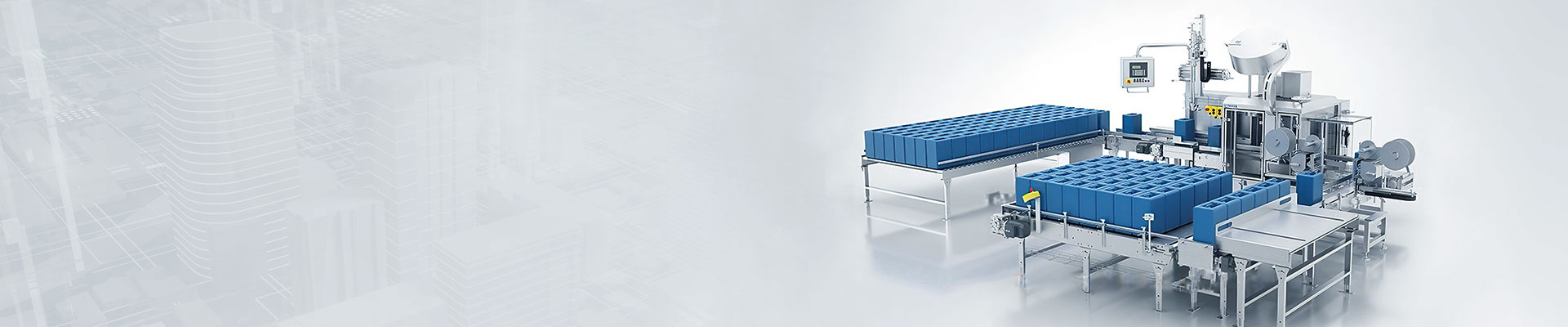


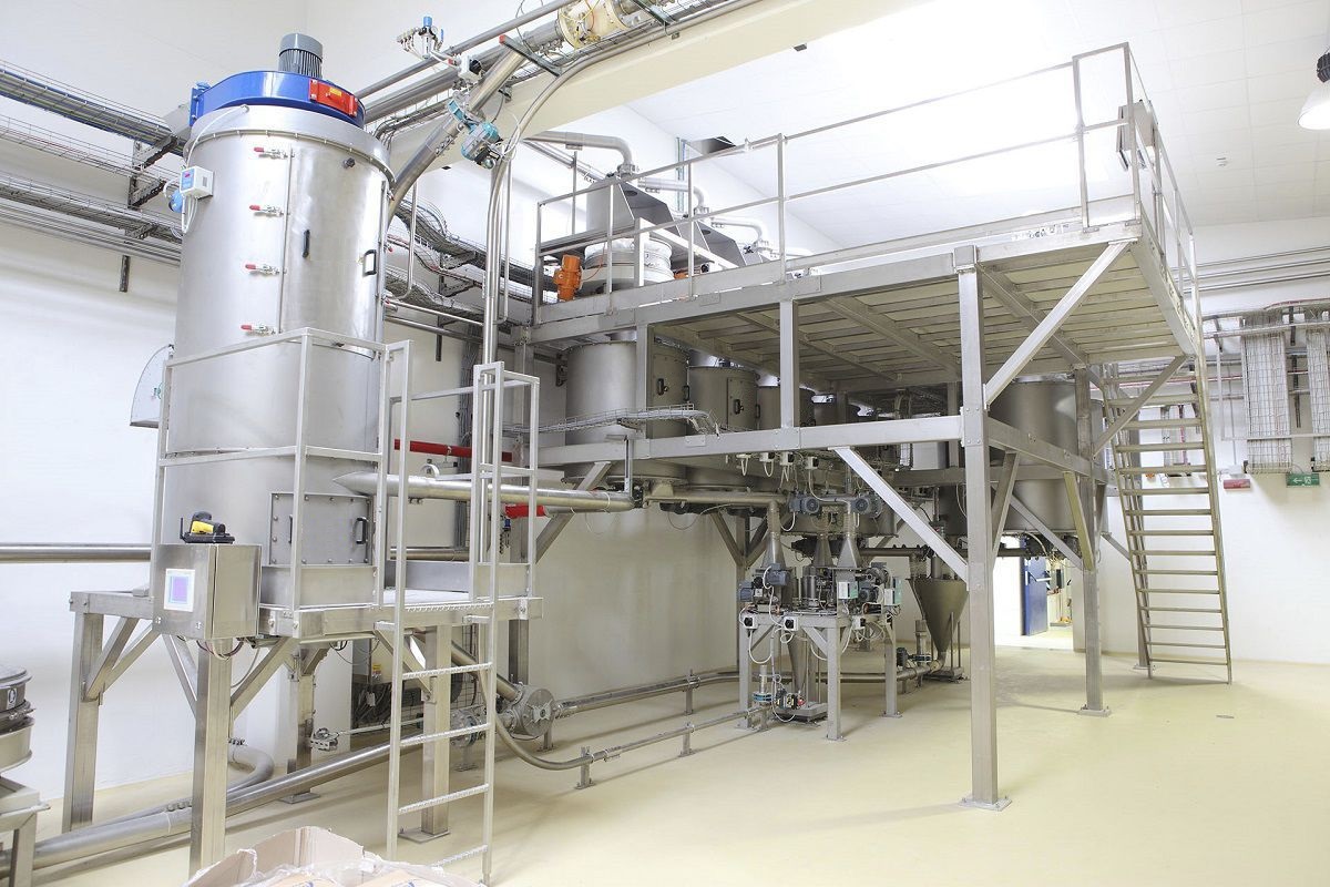


The automatic feeder installs the feeding device and the powder weighing scale and the aggregate hopper under the silo to complete the conveying and metering of materials. The material falls from the bin to the screw feeding device, and when it runs on the feeding device, its weight signal and speed signal are sent to the weighing instrument. Weighing instrument will load weight signal and speed signal through the calculation and processing to get the instantaneous flow and cumulative transport amount of electronic scale, respectively on the weighing display.

 020-34563445
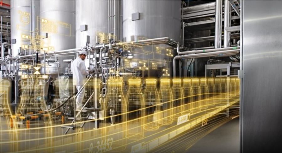
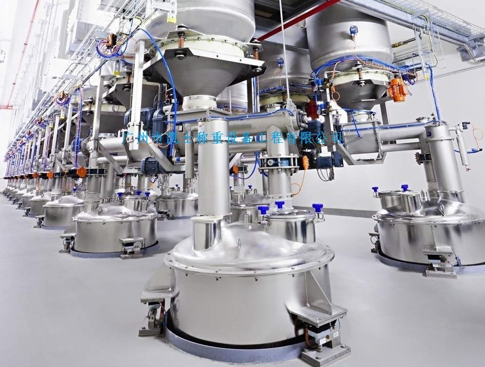
The main task of the feeding system is to mix and feed, and concentrate the raw materials needed for all preparations, which can make all the batching machines share a set of Electronic scales to reduce the system cost and improve the equipment utilization rate, and also save the raw material handling link. The positive pressure thin phase pneumatic conveying method is used to blow the prepared raw materials to the hopper of the batching machine through the conveying pipe. The pneumatic conveying scheme has low production and installation cost and energy consumption. Due to the large scale and complex structure of the feeding system, its components are distributed in the workshop and warehouse, to complete its automatic control, the signals to be detected and the parts to be controlled are both numerous and scattered. The real-time computer network control scheme of advanced fieldbus mode is used to complete the control of the entire system. The pneumatic feeding system consists of two subsystems: mechanical electrical and computer control.
The feeding system is composed of two Roots blower units, meaning feed pipes and several branch feed pipes, pneumatic two-branch reversing valves (hereinafter referred to as branch valves) and a number of cyclone separators. One of the two fans is a backup fan, and each Roots blower unit includes a Roots blower, a typhoon electromechanical machine and a fan control cabinet, whose task is to generate compressed air flow required for pneumatic conveying. The fan outlet is connected to one end of the mixing chamber, and the total material delivery pipe is connected to the other end of the mixing chamber. The feeding system and part of the fan unit and the total feed pipe can be installed in the raw material warehouse. The total feed pipe from the raw material warehouse is connected with an independent branch valve, which can form two branch feed pipes respectively to two workshops. Similarly, n+1 branch feed pipes can be formed with n branch valves, and these branch pipes are equipped with 1 branch valve at the location of each batching machine in the shop (hopper). When selected to feed to a dosing machine, the relevant branch valve is played in the corresponding direction, so that the feed channel is unimpeded, the material can only lead to the dosing machine and can not go to other locations, so that the fan will be the mixture of air and material in the mixing chamber through the various links of the feed channel to blow to the corresponding cyclone separator, after separation, the material reaches the corresponding extruder hopper.


