2020.02.19


Summary:The liquid filling machine integrates bottle feeding, bottle grabbing, filling, capping, bottle grabbing, bottle discharging and other steps, and is controlled through a motion control module.The action sequence of each filling head is determined by position, and then each filling head is started at a certain speed and position.
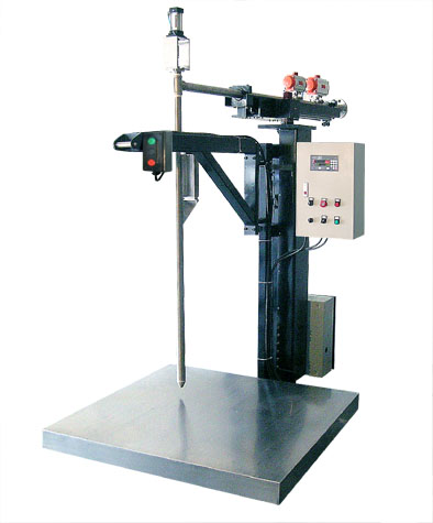
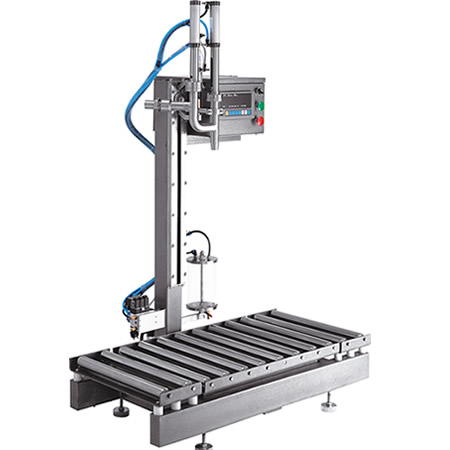
Linear filling machine is mainly used for filling a variety of bottles of paint, suitable for large and medium-sized paint manufacturers. It mainly includes several steps such as bottle feeding, bottle grasping, filling, cap screwing, bottle grasping and bottle discharging, etc. In the bottle feeding stage, 10 bottles are brought in at one time through the belt with 10 fixed clamps, in the first bottle grasping stage, 10 grippers grasp the 10 bottles into the conveyor chain at the same time, in the filling stage, 2 groups of 10 canning tubes can liquid into the 10 bottles in 2 times, in the cap screwing stage, a servo drives 10 cap screwing mechanisms for In the cap screwing stage, a servo drives 10 cap screwing mechanisms to screw the caps, in the second bottle grabbing stage, the 10 filled bottles are grabbed out of the conveyor chain and sent to the output belt, in the bottle discharging stage, the output belt sends out the canned bottles, the servo of each head is controlled by the motion control module. The action timing of each head is accomplished by using position judgment and then starting each head at a certain speed and position respectively. The use of Omron SYSMACNJ series of new-generation PLC after the transformation, the electronic cam function to replace the previous ordinary movement instructions, low failure rate, and it is easy to complete the "pause" function.
2 filling system principle and control
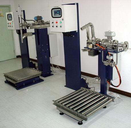
Mainly consists of three major parts: constant pressure liquid tank, bottle clamping and filling head part, frequency conversion conveyor belt part, control function structure. The upper part of the host is the constant pressure liquid storage tank, which has the upper limit level and lower limit level sensor, when the liquid level is lower than the lower limit level, the constant pressure liquid storage tank is empty, and the paint flows into the constant pressure liquid storage tank through the inlet solenoid valve, and when the liquid level reaches the upper limit level, the inlet solenoid valve is shut down, so as to make the liquid level remain stable.
Filling control function structure
Below the constant pressure liquid storage tank is the bottle clamping and bottling head section, with a total of 20 filling heads. The bottle clamping device is driven down by pneumatic cylinder, after falling in place, the bottle clamping device is clamped and positioned by another group of cylinders, and the falling and clamping are controlled by travel switches. After clamping and positioning, the filling head is driven down by the third group of cylinders, and when it is in place, the solenoid valve of the filling head opens and starts to fill the liquid, and the solenoid valve closes after a delay, so as to achieve the filling capacity control by controlling the opening time of the solenoid valve.
Bottle release action process conveyor belt motor is controlled by frequency converter to realize stepless speed change to achieve the purpose of economic operation. After the motor starts for 1s, the bottle feeding cylinder retracts and starts to feed bottles, and after 3s, the cylinder extends to block the empty bottles at the bottle discharging place. The photoelectric switch is set at the bottle feeding place to detect the number of bottles to be fed, and the conveyor motor stops when the corresponding number is reached. The filling head descends to the mouth of the bottle, and the PLC controls the opening time of the filling head by the time inputted through the touch screen. After the filling is finished, the filling head rises and the bottle clamping device relaxes and rises. The cylinder at the bottle exit is retracted and the transfer motor starts to rotate again, after 1s the cylinder at the bottle entry is retracted and the photoelectric switch starts to detect the number of bottles entering again. In this project, there are several points that need to be studied:
Electronic cam instead of timing control;
Pause function;
Work position judgment;
Return to zero stop;
Emergency stop protection;
Linear handling of cranks;
Transformation of cam table.
Among them, the pause function and the linear processing of the crank are the functions that the customer's old equipment failed to realize in the past.
3 Filling solution
Filling function realization
Electronic cam instead of timing control to "into the bottle level" as an example, the master head for the virtual head, from the head for the real head. Filling machine 5 timing control master head to 360 for a cycle, the cycle speed control. The master head and slave head are at zero position. The slave head does not start at the beginning, but starts when the master head position reaches 285, and the slave head stops when the master head position reaches 360. In the next cycle, when the master head reaches 120, the slave head starts to return (reverse), and when the master head position reaches 220, the slave head stops (goes back to the zero position). The bottle feed horizontal head and the master head form an electronic cam.
Offset program
Explosion-proof filling machine through the MasterOffset to offset the master head back 280, then the action sequence and cam shape in line with the process requirements, but it should be noted that this time, the slave head starting position is not 0, which will result in the starting speed of "infinity", which triggers the servo alarm. By setting MasterScaling to 280, the starting point of the slave head can be postponed to the position of "master head 280", and when the master head is started, the slave head will not be started but will wait until the master head reaches the position of 280 before it is started, so that the customer's process requirements can be realized.
Pause function compared to the previous CS, CJ to do the weighing and filling machine, a very important highlight is that it is easy to realize the "pause function", the specific program adopts the speed control instructions to 360 for the cycle cycle of movement, pause function program 2 when you need to pause the device, just execute the MC_Stop instruction. When you need to pause the device, just execute the MC_Stop instruction. When start again, just execute MC_Velocity instruction again, the device will continue to run from the current stop position. The advantage of the pause is that when the operator needs to temporarily stop the equipment, do simple processing, and then need to quickly restore the production state, do not need to find the origin again. It helps a lot to improve the production efficiency.
Workstation judgment on each row of templates should be clamped 10 bottles for filling, capping, capping, screwing, judging the lack of caps and other processes, but due to a variety of objective circumstances (air ducts and other issues), and can not guarantee that every time the clamping of the full 10 bottles. When less than 10 bottles, the whole row can not carry out any operation, otherwise the equipment will produce serious malfunctions (such as no bottle capping will jam the template).
Zero stop When the stop button is pressed, the final stop position of each head must be its own "origin", so that at the next startup, there is no need to search for the origin again (the whole zero return takes longer). On the other hand, if all the heads are at the origin, there will never be a "crash" phenomenon, otherwise if one of the heads stops without being at the origin, the other heads will easily crash into it in the process of returning to zero. Back to zero to stop the method using the Cam_Out instruction, the program back to zero to stop the program, when you need to stop the main drag head, you must wait for the main drag after the completion of the current action. According to the position judgment of the virtual head, when the virtual head is between 90 and 140, the main drag is in the state of stopping, then the execution of the MC_CamOut instruction, you can take off this from the head smoothly out of the cam table. In the process of starting and stopping, a special attention must be paid to one issue, that is, the zero return stop and the same as the starting process, must be executed in strict order.
Emergency stop protection is a very important part of the overall design for "crash" protection. If all the heads are able to move in strict accordance with their own cam curves, and if the heads that are not hooked into the cams are also able to move normally, a "crash" will not occur in principle. However, the probability of a "crash" increases due to a number of factors such as servo failure and cylinder failure. The "crash" situation can be divided into two categories, one is the "cam action" internal collision, the other is the cam action and non-cam action between the collision. For example: into the bottle gripping mechanism and the bottle feeding belt, because the origin of the bottle gripping bottle is located in the bottle feeding belt above, move down to put the bottle needs to be horizontal and vertical head of the two simultaneous action, in order to bypass the belt. If at this time into the bottle horizontal head for various reasons did not act, only the vertical head in action, the air claw will be directly smashed in the belt, resulting in serious damage to the equipment. This belongs to the cam action internal crash. Another example: when the cap screwing mechanism for screwing the cap, screwing the cap claw gripped on the bottle, if this time the drag plate starts to move ahead of time, the bottle will be pulled out of the bad, and even the template will be overturned. This is a collision between the cam head and the non-cam head. In order to avoid these problems, a series of programs have been written. Out of the bottle template space protection program is the space protection of the inlet and outlet bottle template, when the template is jacked up by the cylinder, the template can never be dragged, otherwise it will be overturned. It is still adopted here to judge the slave head by judging the position of the master head. When the master head position is between 320 and 360, the template is jacked up by the cylinder, and at the same time, the template is separated by the template opening and closing head. If the cylinder suddenly drops at this time, the template will not be able to close in time and will be overturned. At this time, the emergency stop operation can be completed by MC_ImmediateStop instruction.
Linear processing of crank The whole set of equipment adopts a number of crank mechanisms, such as filling, screwing cap lifting and so on. According to the characteristics of the crank mechanism, when the servo rotates at a uniform speed, the vertical speed of the crank mechanism is not uniform, and the vertical position does not change linearly. The filling mechanism needs a relatively stable speed (mainly to prevent liquid splashing), and a linear calibration (can be directly calibrated filling volume by setting the servo position).
It is possible to give different speeds to the filling servo when it reaches each position, and the vertical speed is basically constant by giving "multiple speeds" to the angular speed. The speed change is realized by writing the speed every 10ms. The linear relationship between the servo angular position and the vertical position of the crank is obtained through plane analytical geometry and trigonometric operations. The final realization is that the touch screen can be directly set to "ml" as the unit of the filling volume value.
After the cam table is prepared, each head will repeat the movement according to its own cam table data. However, if the product is changed (mainly due to a change in bottle size), the movement of the individual heads will change. For example: the 220mm high bottle replaced by 300mm, then out of the bottle release, the gas claw from the height of the conveyor belt should be increased, which requires the cam table can be transformed through the program, FOR loop statement loop variable, through the FOR loop statement, the cam table will be a number of points change in turn, and then through the following instructions for preservation, so that the head from the head will be in accordance with the new cam table to carry out the movement now.
4 Conclusion
Through the weighing and filling site commissioning and the customer's trial production, all the control requirements of the solution have been verified to meet the customer's transformation needs, and the results are good.