
 2020.02.17
Summary:The automatic filling machine combines the communication mechanism between WINCC and PLC with the configuration plan of the host computer, and uses the Ximen Yu configuration software WINCCV73SIC7V55 communication software to realize the display and process control of the host computer monitoring screen during the automatic paint filling process.
0Introduction
Paint industry has developed more rapidly in recent years, paint as a chemical liquid industry, belongs to the flammable and explosive medium, it is difficult to realize the manual operation of the production process. Enterprises urgently need to increase the level of automation in the canning process to improve the competitiveness in the market.
PLC is a multi-type, miniaturized automatic control technology development of a new generation of industrial new control device, using digital computing, the implementation of control logic, arithmetic operation will count the results of digital or analog through the input/output channel, a variety of switches and buttons, sensors, the field and other signals collected and then through the function module to control a variety of industrialized actual production process.WINCC WINCC configuration software is on the computer in the use of operating system monitoring and debugging, the operation of the screen and the actual production requirements for the creation of human-machine interface, through the integration of the actual operating system, the use of interface communication will be WINCC configuration software and programming development software combined for use.
On the basis of designing the hardware composition scheme of the coating dye filling system, using Siemens configuration software WINCCV7.3 and Step7V5.5 programming software, it can realize the process control of the coating dye automated canning system and the display of the monitoring screen of the upper computer and the simulation of the process. In terms of automation control, it can greatly reduce the labor intensity of workers and improve the safety of real-time production.1 Structure of Paint Weighing and Filling Machine
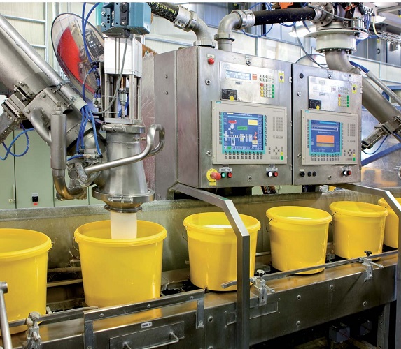
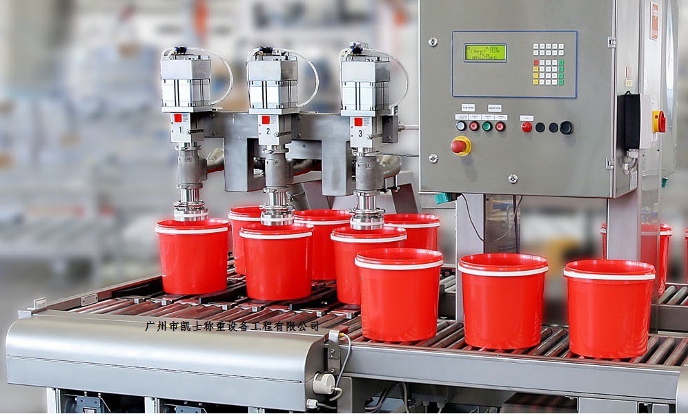
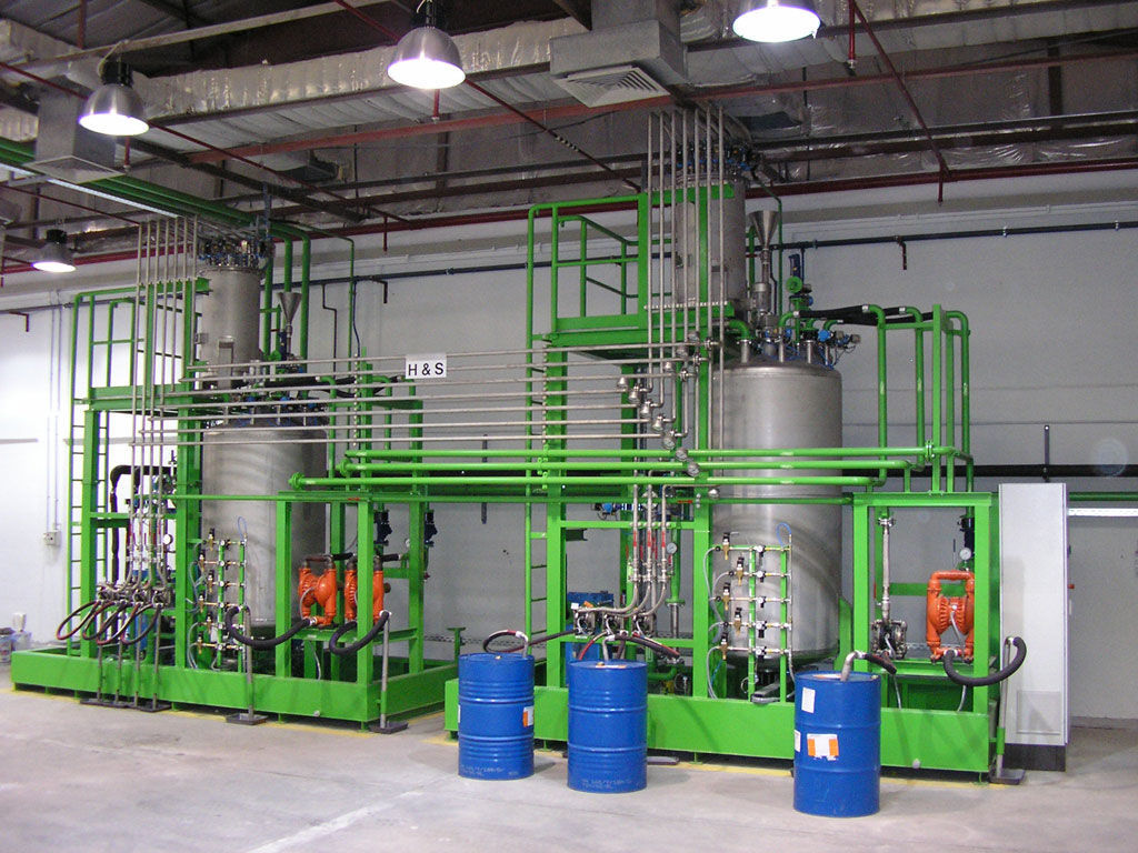
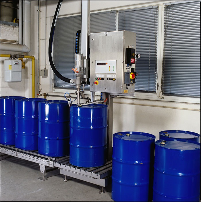
Paint weighing and filling machine production line is specifically as follows
(1) Conveying workstation. The initial station of the production line completes the operation of moving empty bottles from the conveyor belt to the conveyor. Relying on the motor to drive the conveyor belt, move the empty bottles and bring them to the end of the conveyor belt; at the end, the sensor detects and controls the cylinder to push the bottles to the conveyor belt.
(2) Filling station. The core part of canning. Through the sensor to sense whether the empty bottle moved to the work station canning mouth below, the sensor detects the signal, the PLC stops the conveyor, opens the canning head, completes the filling, and the conveyor line starts again. During the system operation, PLC monitors the level of the paint tank, and when it reaches the lower limit, the refill valve opens for refilling.
(3) Capping station. Before the bottle arrives, the cap should be taken beforehand. The use of sensors to determine the location of the bottle cap, to take the cap motor to move to the top of the bottle cap to take the cap: Secondly, after taking the cap back to the top of the forthcoming set of cap station, and so on the bottle to reach this station, through the sensor to detect the bottle, control the drive belt to stop; Finally, by the control of the set of cap motor lifting cylinder, with the rotation of the motor to complete the set of cap action.
(4) Finished product off-line station. By the sensor sensor with PLC counter to complete the counting operation, and then by the clamping cylinder to complete the clamping action. Lifting motor positive rotation, drive the unloading platform to rise, in place, the paint bottle is pushed out by the cylinder, lifting motor reversal, the unloading platform down to complete the unloading".
2 filling system control hardware configuration program
2.1 controller configuration
Automatic filling machine filling system is monitored and controlled by the WINCC upper computer, between the upper computer and the master station through the MPI network communication". The slave station consists of five sub-station controllers for the transportation of the lower can machine, conveyor belt detection, filling and capping station detection, finished product full bottle counting detection, and analog replenishment and feeding function. Among them, the weighing and filling machine master station adopts CP5611 communication card to establish communication with the host computer and slave station, adopts Siemens 300 series new standard type CPU314PLC, and realizes the function of this station by adding signal module. Feeding detection station added analog input output expansion module SM334.
3 filling system PLC program design
3.1 Filling system flow
Self-filling machine through the lower cans of paint bottles conveyed to the assembly line, paint bottles transported to the transport belt, the photoelectric sensor on the transport belt to detect the signal of the bottle, which drives the motor on the transport belt forward; paint bottles along with the transport belt forward transport when the paint bottles are transported to the paint filling station, filling station paint bottles so that the photoelectric sensor detects an input signal, the motor of the conveyor belt to stop running work. When the filling head limit sensor 1 is turned on, it starts to fill the paint bottles; when the filling of paint bottles is completed and the filling head limit sensor 2 is turned on, the motor of the conveyor belt runs again to drive the conveyor belt forward to transport the paint bottles that have been filled; when the photoelectric sensor at the capping station detects the filled paint bottles, the motor of the conveyor belt stops working, and the capping hand limit sensor 1 is turned on to start capping the paint bottles; when the capping of the paint bottles is completed and the capping of the paint bottles is finished, the motor of the conveyor belt stops working and the capping hand limit sensor 1 is turned on. When the capping of the bottles is completed and the capping hand limit sensor 2 is turned on, the finished product is counted full bottle count +1, and the finished product will be transported to the next production link with the transportation belt, and the automatic filling machine will complete the production link again and again when the can lowering machine again feeds the bottles of paint. The paint tank for filling is 50L, when the paint in the tank is less than 5L, the refill valve will be turned on.
3.2 Paint tank level detection program design
Liquid level is an analog quantity, through the A/D conversion, the analog input of 0~10V is converted to a digital quantity of 0~27684, which is collected into the storage area of PLC. In the control program, the analog input signal is first read out from PIW256, and after the data type conversion of the integer of 16, the digital quantity collected by PIW256 is converted into 0.0~50.0L actual engineering value by scalar transformation.
4 Upper computer monitoring system design
Combined with the S7-PLCSIM virtual simulation part, using WINCCV7.3 configuration software in the host computer interface configuration P, to realize the automatic monitoring of paint dye automatic filling machine function. The main functions of the monitoring interface include: canning system, with manual and automatic control of two operating modes switching mode, finished product counting statistics, replenishment level analog detection; configuration of the canning process screen simulation; configuration of the filling process screen simulation; configuration of the capping process screen simulation; configuration of the total screen of the monitoring of the automatic filling machine, the upper computer of the corresponding process running status.
4.1 Create external variables
In the Variable Manager, expand the newly created "s7", and create the following variables in the name column and address column, select the data type as binary variable, the length is 1, and the address is bit memory. In the analog monitoring screen, the upper computer control button selection must be the M area of the intermediate bit memory.
Because the configuration process S7-PLCSIM simulator can not capture the process volume changes in real time, so to establish the following external variables (MD36, MW100-MW116) control screen dynamic display.
4.2 Configuration screen
Select "Graphic Editor", right mouse button to create four named "Newpprocess3" screen, will be Newpdl0.dl0", "" process1, "Pdl as the starting screen", you can realize the paint bottles under the can, transportation, liquid level detection, canning and capping and other actions, and has the function of working status indication. If you need to monitor the working process of each station in detail, you can switch to each sub-screen through the screen switch button.
5 Conclusion
The whole filling machine adopts distributed structure, field layer, PLC control layer and upper computer layer. The upper computer developed in the WINCC environment, realizing the real-time control of the entire process engineering. S7-300PLC as the main controller, through the MPI communication with the upper computer, the field layer to complete the conveyor line, canning and capping process of signal detection and control ah. The application of this system can greatly reduce the labor intensity of workers, improve the working environment of workers and improve safety.


