2020.02.04


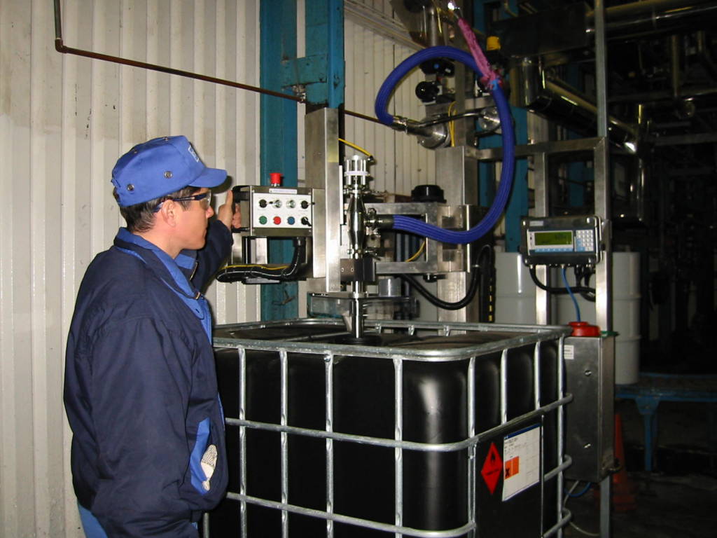
Summary:The liquid filling machine has detailed information for each filling (initial barrel weight, final barrel weight, filling time, start time and end time) that is traceable. It uses wireless filling and weighing wireless networks to make the data Automated collection, analysis and processing are easier.
With the modern industrial weighing field of process information data requirements are also in the direction of networking, timeliness, digitalization and intelligence. In the field of industrial filling machines or filling scales, some process filling system weighing data need real-time storage and background monitoring, often dangerous explosion-proof occasions. Therefore, the installation and laying of the filling equipment weighing terminal network communication pipeline is particularly complex and difficult to construct. Wireless communication is the best way to realize filling weighing terminal data networking. The new wireless weighing network communication technology is characterized by small power consumption, slow speed and short distance, which meets this requirement. More and more filling systems also put forward requirements for real-time storage and monitoring of weighing data. With the standardization and maturity of PLC wireless module network technology platform. This provides a broad prospect for the development of wireless network weighing technology.
1 system design
1.1 Modbus wireless control
With the development of science and technology, the filling machine wireless network gradually replaces the wired network, and the wireless network that only supports static topology is gradually replaced by the wireless network that supports dynamic topology changes. In the field of short-range wireless control, monitoring and data transmission, commonly used technologies include Bluetooth, wireless networks, etc., weighing and filling machine each has its own advantages, liquid filling machine is a low-power, low-complexity, low-cost, low-speed short-range wireless network communication technology. There are many standards in the field of short-range wireless communication, the rapid development of the quantitative filling machine is expected.
Communication is carried out over the network in a message structure that Modbus can recognize. The process of requesting access to other devices, how to respond to requests from other devices, and how to detect errors and log them. A common format for the message field is developed. Modbus network communication must know the device address, recognize the message sent by address, will generate feedback and send it using the Modb2us protocol. On other networks, messages containing the Modbus protocol are converted to the frame structure used on this network.
The master-slave mode, the well-developed answer mechanism and the error frame checking method of the Modbus protocol make Mobus work well in half-duplex communication. Since the Modbus protocol defines a data frame structure that is independent of the physical layer medium, it can be applied to a variety of network types and media. What is used in the system is 433MHz half-duplex wireless communication, which fully utilizes the characteristics of Modbus protocol half-duplex communication. In order to improve the anti-interference of wireless communication, the air rate as well as the interface rate of wireless communication is low, therefore, in order to transmit more data under the same rate, RTU transmission mode is selected in the system, and the advantage of less data in RTU transmission mode makes it less likely to be interfered with in the process of communication, and therefore the communication is more reliable.
1.2 System Structure The filling control system in this paper is a distributed centralized collection and control system.
The overall topology of the system is divided into two layers: the upper monitoring center and the bottom collection and control nodes. The two utilize wireless Modbus protocol for data interaction. The acquisition control node can collect sensor data and transmit liquid meter data, and can control the switch of DC solenoid valve. The acquisition control node has a wireless interface and runs the Modbus protocol. The core of the monitoring center is an industrial computer with configuration software running on it, which communicates with the acquisition control node through the ModbusS protocol to complete the acquisition of sensor data, liquid volume information, and the sending of valve switching commands.
1.3 Monitoring Center
The monitoring center is an industrial computer running Windows operating system. The serial port of the computer is connected to a wireless module with RS232 interface, through which wireless communication is carried out with the lower collection control node. The filling automation control software running on it is developed using configuration software. As an important branch of the field of automation, configuration software has become an indispensable industrial automation industry composition, its remote deployment technology makes the development of large-scale projects become easy, intelligent graphic technology makes the development of graphical user interface is more beautiful and more operable. The configuration software has Modbus protocol interface, which can be easily integrated with the research meter reading system to complete the rapid development and deployment of the system. According to the design requirements, the designed filling automation software has the functions of data acquisition, data processing, data distribution and equipment control. The specific functions are summarized as follows:
System testing and initialization: for the communication and operation status of the system, it completes the initialization settings of the filling system, such as serial port settings, initial value settings of the liquid meter, alarm limit settings, user login settings and so on;
Automatic metering and billing function: independent metering and billing for individual user's liquid consumption, displaying the cumulative liquid consumption of the user, so that the administrator intuitively understands the user's liquid consumption;
Data management supply function: manage user information, liquid consumption information, load cell data, etc;
Query and statistical analysis function: the use of charts and graphs enhances the ability to analyze data, using a variety of graphics to enhance the expressiveness and intuition of the data;
Filling automatic control function: automatically control the switch of the valve according to the collected weighing module data or filling schedule to realize automatic filling.
1.4 Acquisition control node
The field collection and control node adopts modularized design. According to the system design principles proposed in the overall program and the function definition of the field collector, the following discussion focuses on the design of several major circuits as well as the software design.
1.4.1 CPU Unit
The CPU unit selects ATMEL's new AVR series low-power controller ATmega168. ATmega168 microcontroller has low power consumption, good anti-jamming, high reliability, strong analog interface, good code confidentiality, and the price is low, so it is very suitable for the system's data acquisition and communication. In addition to the microcontroller, the CPU unit also includes a key reset circuit, a program download JTAG interface, an external crystal oscillator circuit, and a program run indicator circuit.
1.4.2 Output Control Unit
In order to reduce the power consumption of the system, the system control object is selected as a DC latching solenoid valve that only needs power supply for the opening and closing moments, and the solenoid valve needs to be driven by positive and negative pulses, with a pulse voltage of 9 V and a pulse width of 30 ms. An H-bridge driver chip, L9110S, is used in the design to generate the positive and negative pulses. Because the solenoid valve action moment, the current is relatively large, so in the solenoid valve drive circuit is placed next to a 1000μF capacitor to provide some instantaneous current.
1.4.3 Explosion-proof battery power supply unit
The hardware devices in the system are powered by a combination of explosion-proof batteries, and the power supply unit includes batteries, charge controllers, and power conversion circuits. Solar charge controller can also be used PHOCOS CML0502 type explosion-proof controller, selected solar panel power of 10W, explosion-proof battery for 12AH maintenance-free battery. The power conversion circuit uses two linear power supply chips to convert 12V voltage to 9V and 5V, respectively, for the solenoid valve drive circuit and microcontroller system power supply.
1.4.4 Software Design
RTU communication mode was selected for this design and some functions suitable for this collector were chosen for application. The communication software design involves variable names, variable data types, register types and corresponding register bias values.
In order to improve the response speed of the interrupt, after all collectors serial port interrupt to receive information frame data, only two parts of the operation of CRC checksum and address recognition are carried out in the processing of the received data, if the transmitted data does not satisfy the CRC checksum, all the collectors do not respond, and when the CRC checksum is correct, each collector will recognize the address information, and the collector that is compatible with the address will set the flag bit, which will be detected by the main program in the cycle of the The main program detects the relevant flag bit in the loop and calls the communication subroutine for processing.
2 system implementation
Liquid filling machine for each filling has detailed information (initial barrel weight, final barrel weight, filling time, filling time, start time and end time), metering filling device these information are traceable, can better avoid common deception or favor. The filling control program of the automatic filling machine will judge and record some abnormalities in the filling process to prevent illegal operation by filling personnel. During non-normal working hours, the lock control valve of the filling machine is locked by a person, which can effectively prevent unauthorized filling.
When the liquid filling machine fills in batches, the filler only needs to record the number of times the filling is started and the total number of iron drums on the special receipt. Detailed filling information (e.g. specification, initial weight, final weight, filling quantity, etc.). It is automatically transmitted directly to the financial computer through the internal wireless network without manual intervention. Customers can fill in the receipt for payment.
The finance department enters the receipt number information on the receipt slip, and the filling equipment automatically calculates the receipt amount and prints the receipt voucher in duplicate. The receipt voucher should record the customer's name, specification, quantity and number of drums. The customer should use one copy of the receipt as a receipt and the other copy should be submitted to the inspector as an export license.
The guards checked the specifications and quantity of iron drums on the export license before releasing the goods. The financial system automatically collects the filled statistical filling data and detailed information on a daily basis and reports it to the parent company's computer system on a regular basis.
3 Conclusion
The wireless filling system based on Modbus protocol is suitable for industrial filling automation control applications, and its communication success rate and data transmission accuracy meet the design requirements. In addition, the system is characterized by economy, ease of use and scalability.
This research has developed a first-scale and scalable filling automation control system by combining independent research and development and system integration, and the construction of the system has realized the informationization, remote and centralized management of liquid filling, which is of great significance for improving the liquid level and efficiency of industrial liquid management and realizing the modernization of industrial liquid management.