
 2020.02.06
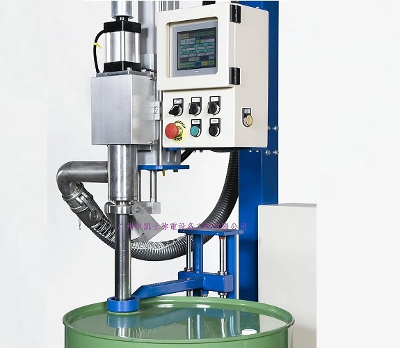
Summary:The automatic filling machine controls the amount of injection based on the weight value read by the AD module. It is mainly composed of a bottle feeding mechanism, a bottle guide mechanism, a transmission mechanism, a tracking mechanism and a filling mechanism.By changing the output frequency of the frequency converter, the purpose of motor speed regulation is finally achieved.
0Introduction
With the development of society and the progress of science and technology, the enterprise production line has higher and higher requirements for the intelligentization of filling equipment, and there are higher requirements in filling accuracy, system stability and online quality detection.
In this paper, an economic filling equipment with automatic detection function is designed to realize the functions of bottle feeding, filling, sealing, detecting and conveying of packaging containers through the continuous intermittent movement of each mechanism, and the device is highly accurate, responsive and smooth running.
1Working Principle
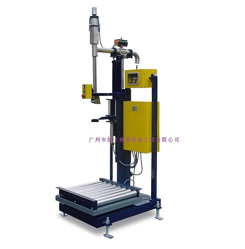
The core of the process of automatic filling machine lies in two filling: pre-filling and supplementary filling. After peeling the empty cans by the filling system sent to the pre-filling below the pre-filling, pre-filling the amount set in advance in the PLC, by the same service motor according to the PLC's pulse command to drive the filling screw for filling. After the pre-filling is completed, the filling system sends the cans to the pre-filling and weighing station, the weighing module weighs the cans (generally in the pre-filling, about 1%-5% of the target weight will be left for the supplemental filling), and the actual value of the weighing is fed back to the PLC, which calculates (supplemental filling quantity = target weight - actual value of the pre-filling weighing) and gives the quantity of the supplemental filling, and the filling system sends the cans to the supplemental filling station to start supplemental filling. The filling system sends the can to the refilling position to start refilling. Supplementary filling is completed by the filling system sent to the supplementary filling weighing module for detection, if the weight is qualified then complete the filling out of the can; if the gap from the target value is large then the filling system is sent to the supplementary filling for the second supplementary filling until the weight is qualified so far as to complete the filling out of the can.
2 filling machine structure principle
Liquid filling machine in the work, materials such as containing gas, or dissolved gas, it is easy to produce bubbles. Often encountered in the filling of materials: must be hot filling materials, filling before the material is not degassing, due to pressure changes and easy to produce denaturation of the material and so on. If negative pressure is generated in the dosing cylinder, air bubbles will be generated in these materials, and residual accumulation in the dosing cylinder, reducing the filling accuracy.
In order to solve the problem of decreased filling accuracy, the ideal method is in each filling stroke in a timely manner in the quantitative cylinder air bubbles out. To this end, the industry has been trying to find a solution, a method is to improve the shape of the quantitative cylinder design, so that the flow of materials in the quantitative cylinder in the flow process generates vortex, which prompted the air bubbles and the inhalation of the liquid material is fully mixed, and then discharged for filling filling. Although the above method to improve the filling accuracy has some help, but can not completely solve the problem of filling accuracy is not high, and in the filling process is prone to produce bubbles and material splashing, resulting in the generation of another major factor causing a reduction in filling accuracy, in order to solve the above problems, it is urgent to develop a quantitative cylinder to prevent the production of air bubbles, but also to solve the air bubbles due to a variety of factors caused by the filling accuracy of the filling of filling Filling valve system. The Shikoku Company in Japan has recently developed a new type of high-precision liquid quantitative filling valve system, which can effectively eliminate air bubbles and material splashing and other problems generated during the filling process, thus ensuring high filling accuracy.
1) Filling valve structure
The quantitative filling filling valve system is composed of three cylinders or cylinders (upper cylinder lower cylinder, control cylinder), two one-way filling valve (upper filling valve, lower filling valve), a quantitative cylinder and piping and other accessories.
The storage tank is located in the high position by the pipeline and the upper filling valve connected to the upper filling valve by an elastic membrane is divided into two parts, can be separated from the material and the action of the upper cylinder to ensure that the material hygiene. The lower part is the main body of one-way filling valve with spring reset, which is connected with the storage tank and dosing cylinder. The upper part of the filling valve is installed with the upper cylinder, the piston rod of which controls the opening of the upper filling valve through the action of the elastic membrane. In the upper part of the upper cylinder is also installed a control cylinder, through the cylinder can determine the upper cylinder piston rod stroke for the size of the two ways, and then control the upper filling valve open mouth size.
The quantitative cylinder is connected to the outlet of the upper filling valve, and connected to the lower filling valve 7 through the pipeline, and through the piston movement, to realize the quantitative inhalation and discharge of materials. The structure of the lower filling valve is basically the same as that of the upper filling valve, but there is no control cylinder installed. The lower part of the lower filling valve is the filling head, and the material is filled into the container through the outlet of this filling head. The outlet of the filling head is equipped with a mesh grille, which prevents the material from leaking under its own weight by means of the surface tension of the material. When the filling valve system is in the cleaning mode, the outlet of the filling head can be connected to a spare cleaning hose connector.
2) Filling valve working principle
The work of the filling valve is divided into two states: filling state and cleaning state. The opening and closing of each filling valve and the suction and discharge of the material by the dosing cylinder are carried out by the control system according to the design requirements and the specified beat and phase.
In the filling working state, the piston of the control cylinder is located in the outstretched position, and the movement of the piston rod of the upper cylinder is determined to be within the range of small stroke, so that the one-way filling valve is in a small opening degree. When sucking materials, the piston rod of the upper cylinder extends to open the filling valve of the upper filling valve, the piston rod of the lower cylinder returns to reset, so that the filling valve of the lower position is closed, and then the piston of the dosing cylinder retreats backward, and the materials are quantitatively sucked into the cylinder. At this time, no filling filling to the container. When filling, the piston rod of the upper cylinder is returned to reset, closing the filling valve of the upper position, and the piston rod of the lower cylinder is extended to open the filling valve of the lower position, and then the piston of the dosing cylinder is moved forward to send the material therein, and the filling is filled to the container through the filling valve of the lower position.
In the cleaning working state, the piston of the control cylinder is returned to reset, limiting the piston rod movement of the upper cylinder to a large stroke range, so that the one-way filling valve is at a large opening. The movement of each filling valve and cylinder is the same as that in the filling working state. This state can increase the flow and flow rate of cleaning liquid and improve the cleaning effect. In addition, before the filling operation, such as in the filling filling valve piping system accumulated air, can also be used in this state of operation, the use of large strokes will be quickly discharged from the system air.
3) Characteristics of the filling valve
Since the filling valve system opens the upper filling valve when the material is sucked into the dosing cylinder and closes the upper filling valve when the material in it is discharged, it will not generate a large negative pressure inside the dosing cylinder due to the material sucking in, and it can effectively prevent air bubbles from being generated during filling. The filling valve has the following advantages:
(1)No air bubble and no splash when filling, high filling precision;
(2) High-speed filling can be realized due to good filling status;
(3) Liquid materials sent to this filling and filling valve system can be ideally filled even if the venting is incomplete;
(4) The design of the filling valve can be unconstrained because it is not affected by the volume and shape of the dosing cylinder.
In this filling valve, when the one-way filling valve is in large opening, the piping system of the filling valve can be cleaned and the air in the filling valve system can be removed. When the one-way filling valve is in the small opening, the filling operation can be carried out. The structural features in addition to high efficiency, rapid and smooth cleaning of the system and remove the air from the filling valve, in the filling operation, it is also easy to realize the dosing cylinder piston movement of the beat and one-way filling valve opening and closing beat synchronization.
3 The overall structure and workflow of the rotary automatic filling machine
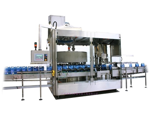
Automatic filling machine consists of rotating mechanism, filling mechanism, hanging cap mechanism, capping mechanism, detection mechanism, conveying mechanism and other parts. The filling process flow is as follows:
1)Container bottles enter the rotating disk through the feeding mechanism;
2) The rotating disk rotates 30° each time, and other institutions do not perform actions during the rotation;
3)The rotation stops, the empty container bottle is in the filling station, and filling is carried out during the stopping time;
4) The filled container bottle is rotated to the sealing station, and the sealing of the container bottle is completed by hanging and screwing action;
5) Automatic detection after the completion of capping, one by one to determine whether the quality of encapsulation is qualified;
6) Container bottles are separated from the rotating disk, unqualified products are automatically rejected on the discharge conveyor belt, and qualified products are transported to the next process.
3.1 Mechanical structure
1) Rotating mechanism
The rotating disk is a circular structure, with U-shaped grooves evenly distributed around the circular arc, with an interval of 30°. Driven by a servo motor to realize intermittent rotation, every 30 ° turn there is a container bottle into the U-shaped groove, and drive the container bottle rotation to the next station.
2) Filling mechanism
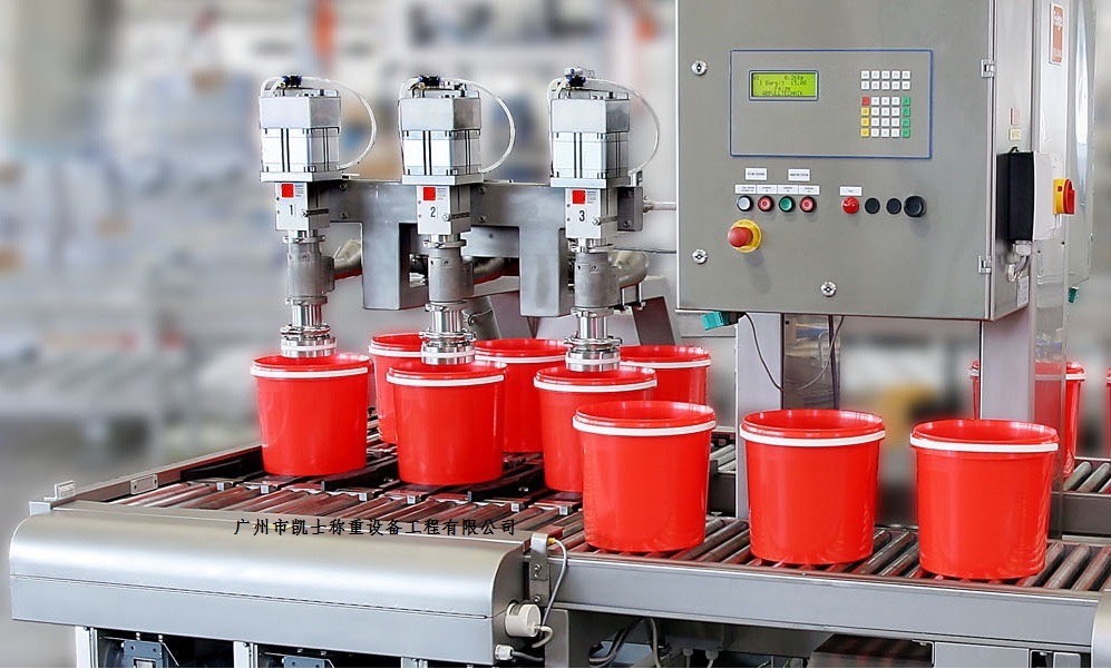
The liquid filling mechanism adopts anti-drip filling technology, the liquid conduit adopts high-quality silicone tube, the inlet port has a filter function, and the outlet port adopts anti-drip filling head.
Bottle feeding detection is set up in front of the filling station, under the premise that the sensor detects the presence of container bottles, automatic uniform filling is carried out according to the requirements, the filling speed and time are adjustable, and the repeated filling error is ≤1%.
3)Cap hanging mechanism
The collated bottle cap enters the chute in sequence, and is stopped by the spring stopper at the end, and forms a certain inclination angle, and the rotating disk stops when the container bottle is rotated to the cap directly underneath it, and the cap is driven to move by the body of the bottle during the rotation of the rotating disk, and the cap is realized to be hung up under the pressure of the spring pressure plate on the upper part.
4) Capping mechanism
After the two cylinders 2 of the capping mechanism clamp the container bottle on the work station, it is driven by cylinder 1 to move up and down, and when the round top bar contacts with the bottle cap, the top plate will be pushed upward due to the role of the cap's reverse force to drive the three rotating claws to realize the holding action, and at the same time, the cap will be rotated by the motor rotation and screwed up.
4 Encapsulation detection
Bottle cap encapsulation good or bad directly affects the liquid in the container bottle sealing effect, high cap and crooked cap can not be a good bottle of beverage sealing, can not meet the requirements of quality assurance, and no cover container bottle are as substandard products.
The system designs a detection algorithm based on the range sensor to detect whether there are defects of high and crooked caps one by one, and at the same time, the fiber optic sensor detects whether there is no cap phenomenon, the defect detection rate can be up to 99.5%, and the defective products will be automatically labeled after the detection. After the detection, the container bottles are separated from the rotating disk into the conveyor mechanism, according to the aforementioned detection results, the rejecting cylinder will push out the substandard products into the conveyor belt for online rejection, and according to the type of substandard recycling.
5 Conclusion
The automatic filling machine designed in this paper is used in the liquid filling industry, with simple structure, high efficiency and practicality, using servo motors, distance sensors and PLC control technology to realize automatic filling and online inspection functions. This device is suitable for filling containers of different types, materials and sizes, and has broader application prospects in the pharmaceutical and other filling industries.


