2022.09.23


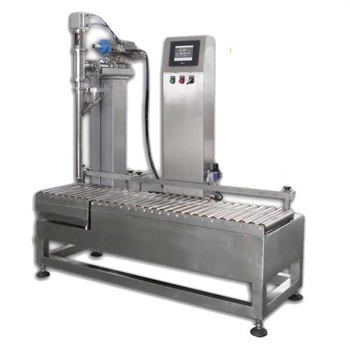
Summary:Automatic filling machine When the liquid level in the liquid storage tank is at or below the lower liquid level (lower limit value), the float pressure plate breaks away from the mechanical valve and the pneumatic butterfly valve opens, and the liquid is transported into the liquid storage tank through the feed port.
Automatic filling machine when the liquid level in the storage tank in the lower liquid level (lower limit value) and below, the float pressure plate from the mechanical valve and pneumatic butterfly valve open, through the inlet to the storage tank to transport liquid materials, with the liquid level continues to rise, the float assembly according to the direction of the arrow to rotate, when the liquid level in the storage tank to reach the upper liquid level (upper limit value), the float pressure plate to press down on the mechanical valve contact and the pneumatic butterfly valve closes, to stop to the When the liquid level in the liquid tank reaches the upper level (upper limit value), the floating ball pressure plate presses down the mechanical valve contact and the pneumatic butterfly valve to close, stopping the delivery of liquid materials to the liquid tank. The filling system is controlled by pneumatic control valve, mechanical valve and pneumatic butterfly valve. Pneumatic control valve is normally open type, mechanical valve and pneumatic butterfly valve are normally closed type. When the air source is opened, the air through the air control valve will directly open the pneumatic butterfly valve, the liquid through the butterfly valve is transported to the liquid storage tank. When the liquid level in the reservoir reaches the set maximum value, the float pressure plate presses down the mechanical valve contact to shift the mechanical valve, and the mechanical valve shifts the air control valve to close the pneumatic butterfly valve, stopping the delivery of liquid to the reservoir. With the filling, the liquid level in the reservoir tank continues to fall, when the liquid level in the reservoir tank reaches the set minimum value, the pressure plate to leave the mechanical valve contacts, mechanical valve, pneumatic valve reset under the action of the spring, the pneumatic butterfly valve is open, the liquid through the pneumatic butterfly valve and re-conveyed to the reservoir tank. This cycle is repeated.
Automatic filling machine can flexibly choose a variety of filling methods according to the actual situation, real-time communication between the management center and the filling system, filling records are uploaded wirelessly to the management center database, the electronic scale itself can also be stored offline 8000 filling records. It can display the filling data information of each barrel and the daily filling quantity; it can count the barrel filling information by time period, barrel specification and batch, etc.; according to the barrel barcode, it can manage the traceability of each barrel. No need to install and maintain communication lines, ready to use, automatic tare, automatic zeroing of the scale, automatic cut-off at the set quality. With total, net, standard 3 kinds of filling mode and automatic and manual 2 kinds of filling mode, according to the current quality of the scale platform, automatic matching barrel type function.
The liquid filling machine consists of a business layer composed of filling electronic scales, a data transmission layer composed of wireless base stations, and a data management layer composed of a back-end server. The ZigBee communication module of the filling electronic scale receives the filling records generated by the filling scale in real time and sends the filling records to the base station. After obtaining the token from the server, the base station polls the filling scales under its jurisdiction within a time slice. If the wireless communication module of the filling scales has data to be sent, it must wait for the query local command from the base station before sending it, or it will not make any response. The base station is responsible for relaying the collected information. The filling electronic scale is responsible for the reading of the barcode of the filling barrel, the processing of the filling process and the display of the information, and needs to transmit the filling records to the ZigBee base station. The base station is responsible for receiving and forwarding data, i.e. the data received from the ZigBee communication module is put on the CAN bus, and the data received from the CAN module is sent out through the ZigBee communication module. The selection of the main controller needs to take into account the functions realized by the current system, future upgrades and expansion, as well as cost and other factors. S3C6410 is selected as the base station controller. S3C6410 is a microcontroller based on ARM11 core, with a main frequency of 667 MHz and rich on-chip resources. Select NXP LPC2388 as the main controller of the filling electronic scale, the device is based on ARM7TDMI-S core processor, with a USB controller, SPIIC UART interface and other rich peripherals, can meet the needs of the filling electronic scale.
Liquid filling machine in the filling process of the identification of the barrel identity is an important guarantee of the barrel filling information management, the use of portable scanners to scan the barrel to be filled one by one bar code, the weighing module will be sent to the server to obtain the bar code data barrel profile data, and then through the weighing module sent down to the filling scale, the weighing module storage to improve the performance of the filling with a compatible USB2.0 protocol controllers, using the The K9FXX08 series NAND FLASH chip is used to store the bucket file data. The bucket file data can be updated individually or in batches, and is stored in the FLASH chip through the weighing module interface, so that when the bucket barcode is scanned prior to filling, the bucket file data is read directly from the FLASH, and when the ZigBee communication is not working properly during the filling process, the filling records will also be stored in the FLASH until the next time when the communication is restored. When the ZigBee communication is not normal during the filling process, the filling records are also stored in FLASH and uploaded to the server after the next communication is restored. The data from the weighing module is processed through the serial port, which is responsible for receiving the polling signals from the server to the base station to give the answer information, and if the communication frames are the data frames from the server to the base station, the data from the weighing module will be sent directly to the serial port sending buffer, and the received data will be sent into the serial port receiving area after being calibrated and parsed to ensure the stability of the signals.
The automatic filling scale supplies two sizes of flow to supply material to the weighing drum. The weighing module converts the weight signals into electrical signals and transmits them to the weighing controller. The weighing controller measures the weight value and the program controls the entire weighing process, configuring the switch input signals to include the start button, shutdown button, bucket door status and other detection signals. The switch outputs are control signals (e.g. thickness feed solenoid valve, exhaust solenoid valve, bag clamping, etc.), weight indicator, alarm output signals. The digital channel receives the weighing module weight input signals. Among them, the weighing drum door closure and clamp back clamping test are proximity switches, and the buffer zone door, weighing drum door, and clamp back cover are actuated and controlled by solenoid valves. Ideally, the large supply is the small supply and together they accomplish 95% of the rated weight value in a very short time. Then the big supply stops and the small supply produces another 5% 10% of the rated weight value, taking a much longer time. In actual production, the weight and time parameters of these two segments must be constantly adjusted to the situation in order to achieve the optimum.
When verifying electronic scales in the measuring department, both their static and dynamic accuracy should be checked. In actual production, the measurement accuracy of the product mainly depends on the dynamic accuracy. The dynamic accuracy errors analyzed in theory and actual debugging and production mainly occur in the internal and external environment of the automatic filling machine. The internal faults of the automatic filling machine mainly include:① Weighing module failure. ② weighing indicator failure; ③ control factors and implementation factors delay error. External environment errors mainly include:① material uniformity, lumpiness; whether the punching is uniform or not ② whether the equipment is affected by external power or vibration interference.
Once two indicators are installed in each fill line, they can be run on one of the electronic scales (e.g., a scale). xq, x1 automatically signals the opening of the large and small valves in a scale. The last pre-supply in the large ginger valve enters the weighing drum. a-level high-speed supply screw starts the supply, and when the weight of the high-speed supply (low-speed supply at the same time) reaches the set value, the high-speed supply is signaled to stop by X0. a-scales' large valves are closed. The rapid supply screw stops after a delayed operation of 2S. At this time, the fast filler will disengage from the large valve to form the next pre-fill volume, thus speeding up the supply. The small supply screw will continue to supply at the actual value. At the same time, the small valve supply screw stops at the same time. a The scale sends an X2 discharge signal to the PLC after the scale judges itself that the weight has passed. Then the photoelectric switch will check whether there is any bag in the filling bag box, if not, an alarm message will be sent, and the up and down shaking of the cylinder-driven suction cups will automatically catch the bag and put the bag onto the traction plate with toothed belt drive, and then turn to the positioning platform. After the filled bag passes between the upper and lower suction cups, the cylinder driven suction cup sucks the bag inlet and the cylinder drives to cover the tank. the PLC thinks the bag holder is closed. Immediately cover the bag. Scale does not reduce. Delay 3S signal to open scale door to drain. 1S delay to close scale door to prepare for next load. The electronic scale determines that the scale is empty by weighing the weight weighing module. if x0 is sent again within tolerance, the Xi signal will restart the supply process. Otherwise, an excess error will indicate stopping the provisioning. PLC special data storage with adjustable size via PLC potentiometer opens the bale clamp and determines the delay time. The sew-on bale machine picks up the sewn bale and places the bale in the pipe transporter. the b scale also works like the a scale. These two scales and a PLC consist of a weighing and filling automatic filling machine that can continue to work in the case of manual assembly, thus increasing efficiency. In order to prevent both scales from placing material at the same time, an interlock feature must be incorporated into the process.