2022.09.25


Summary:The reaction tank adopts a configuration monitoring interface, and through data collection and processing of the on-site automatic filling machine, animation display, alarm processing, and process control are implemented.Real-time curve, historical curve and report output.
The reaction tank adopts the configuration monitoring interface, through the data acquisition and processing of the on-site automatic filling machine, with animation display, alarm processing, process control. Real-time curve, historical curve and report output. In order to realize the above monitoring requirements, the dynamic filling process is simulated by adopting Haniwa effect and fast flow attribute setting in the monitoring interface design, and the manual/automatic selection, starting, stopping, emergency stopping and manually opening the pump solenoid valve are realized by adding standard buttons, and the setting of filling quality is realized by setting the display output attribute of labels to display in real time, and the number of bottles is set and the number of barrels is displayed at present, and so on. It can complete the monitoring of the operation status of the filling system by setting the label display and output attributes.
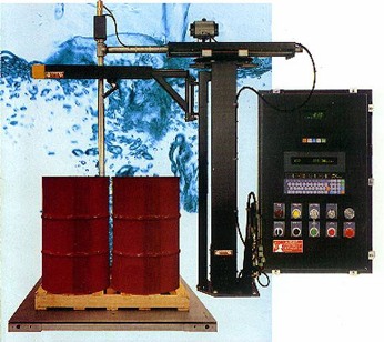
The reaction tank weighing control system adopts the cascade control of filling ratio and reactor temperature and jacket temperature, which is composed of industrial computer, RS232/485 conversion module and filling system, and supports MCGS configuration and communication function. For the industrial control computer, the reactor tank computer system has six switch input variables LIC302H (L), LIC303H (L), LIC304H (L), and if the reed switches are closed, the variable lic 304 h (l) is displayed on the upper (lower) level of TK-A through TK-C. There are nine switch output variables ssv501-ssv507, SSV509, and DRV. of which ssv501-ssv507 and SSV509 reflect the operating status of the solenoid valve. The control commands are issued by the industrial personal computer. The industrial control computer performs signal acquisition and output control of the above 18 variables. Two antenna inputs and outputs, test and analog output fluids are selected as bridges to enable communication between the industrial control computer and the main field filling, and the industrial computer is connected via an RS232/485 conversion module.
Six switch input variables are connected to the input channel of the #1 filler, switch output variables SSV501 through SSV507 and SSV509 are connected to the output channel of the #2 filler, and the mixing tank (DRV) is connected to the output channel of the #1 filler. Two analog input variables are connected to the input channel of Filling Tank #3 and analog output variables are connected to the output channel of Tank #4. The output variables are used to control the corresponding mixing tanks (solenoid valves, mixing tanks and electrical control valves). The switching output variables are connected to the mixing tanks' control terminals via the output channels of the #1 and #2 filling scales, which then control the 24V DC and 220VAC power supply to be switched on or off. The analog output variable "control valve" is connected to the control terminal of the servo mixing tank through the output of the 4# weighing and filling machine, and the servo distribution tank drives the electrical control valve.
According to the control requirements, the filling of the reaction tanks is a sequential process. Set the script program component in the start policy of the MCGS run policy window to write a program that opens all solenoid valves except the feed valve, delays the timer tank startup by 2 minutes, and empties all weighed reaction tanks at system startup. Set the setting of the cycle policy to 200 milliseconds, add the script component to it, and write the control program as described in the flowchart in Figure 3(b). The agitation time is set in the timing tank assembly and can be adjusted according to the time required for filling a complete reaction. Stirring stops when the timing status of the timing tank is changed to "1".
Industrial control computers and electrical control valves constitute the reaction tank temperature-clamp temperature cascade layout system, control methods and control algorithms to select, set the value and related parameters, the reaction tank temperature control real-time curve of the display framework, according to the shape of the real-time curve of the temperature in the reaction tank, intuitively adjusting the integral time and the differential time, weighing the control effect. The incremental number proportional integral differential control formula, where Kd=0 is the proportional integral control formula. Set:PI and PID in the MCGS operation strategy window, and the script program is written according to the formula. Running in automatic mode, then the corresponding control algorithm can be selected from the Control Algorithm drop-down box. Set the relevant parameters to observe the changes in the real-time profile of the temperature in the reaction tank until the control requirements are met. Add the generic filling system to the Filling System window of the MCGS and set the corresponding serial port number and sampling period for the default properties. Four sub-filling systems were added below the filling system. Switch Input Output Filler 1#, 2#, Filler 3#, and Drive Box for Analog Output Filler 4#. In the default attribute settings, the addresses of the above four sub-filling systems are set to 1, 2, 3, and 4. The channel connection variables for weigh tank #1 have digital inputs (DATA) and switched outputs (DRV), with DATA representing the weighted sum of the states of the six switched-input variables, with a weighted value of 2n (n is the channel number) for each input channel. filler #2's
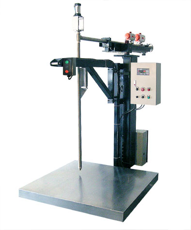
Weighing and filling machine through the weight sensing and input pulse frequency fast and slow realization, when the frequency of the pulse occurs to reduce, the speed of the stepper motor decreases; when the frequency grows, the speed is accelerated. In order to achieve the purpose of measuring size adjustable and improve the accuracy of measurement, the screw speed adjustable and positional positioning accuracy, the use of stepper motor to control the screw speed and number of revolutions, not only simplify the mechanical structure, but also make the control is very convenient. Without overloading, the speed and stopping position of the stepping motor only depend on the frequency of the pulse signal and the number of pulses, and are not affected by the change of load.
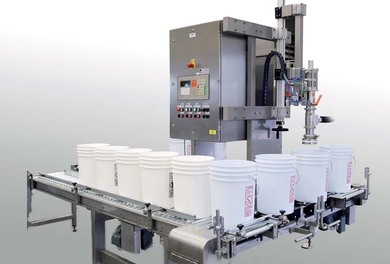
1-4 filling machine control system will be sent to the empty barrel filling position, the mouth of the barrel and the spray gun mouth alignment, press the machine "start" button, the filling machine spray gun in the cylinder driven into the barrel; liquid filling scale when the detection of the spray gun in place, the bottom valve opens, nitrogen valve start will be dry nitrogen through the filling port into the barrel, so that the air in the barrel by nitrogen replacement, while accelerating the nitrogen in the barrel. The air in the barrel is replaced by nitrogen, and at the same time, the drying of the inner wall of the barrel can be accelerated to ensure the safety of filling. Nitrogen filling should ensure that the air in the container is completely replaced, the specific amount of nitrogen filling can be adjusted by the controller time. After a certain amount of nitrogen filling, the nitrogen filling valve is closed, and the control instrument automatically removes the tare weight of the empty barrel on the scale, and then the fast and slow dosing ball valves are opened at the same time; the first fast dosing, the spray gun stays for a period of time at the lowest position of the drop and starts to rise up to fill under the liquid level, and stops at the mouth of the barrel in the middle with the rise of the liquid level in 3 places, and then the slow dosing; the ball valves and the bottom valves are closed when the filling volume reaches the preset advance volume; the spray gun rises up to the outside of the barrel. When the filling quantity reaches the preset advance quantity, the ball valve and bottom valve will be closed; the spray gun will rise to the outside of the barrel. Through the screen real-time display of the current filling quality, filling the number of barrels and other on-site work status, you can carry out the corresponding operation on the upper computer, through the interface for the filling mode selection and start, stop and other buttons operation. It is possible to change the filling quality, the number of barrels and manually remove the tare (i.e., the quality of the filled bottles) when using different filling barrels. In order to realize the above monitoring requirements, the monitoring interface simulates the dynamic filling process by adopting Haniwa effect and fast flow attribute settings; it realizes manual/automatic selection, starting, stopping, emergency stopping and manually opening the pump solenoid valve by adding standard buttons; and it realizes the real-time display of the filling quality settings, the setting of the number of barrels and the display of the number of barrels, etc. by setting up the display output attribute of the labels, and it also realizes the monitoring of the running status of the filling system by setting up the monitoring screen. Filling system operation status monitoring.