
 2025.05.07
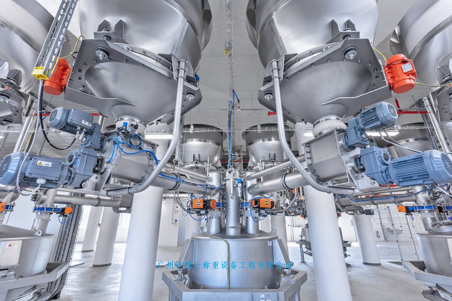
Summary:It is a feasible method to use hydraulic calibration device to calibrate the hopper scale. The hydraulic calibration device consists of a set (including 3-4 head) hydraulic jack device, a set (including 3-4 head) pressure sensor and a digital display. A small platform for placing pressure sensors and hydraulic jacks is welded above the vertical axis frame of the hopper scale weighing module. The lower part of the platform support is welded directly to the weighing frame of the hopper scale weighing module, and 3 (or 4) pressure sensors are connected to the display. The upper part of the jack gently touches the upper part of the platform support, and the display shows zero. The hydraulic jack pressure device simultaneously exerts pressure on the 3 sides (or 4 sides), and the load is uniformly applied to the pressure sensor and on the scale body. The load value read out by the display of the hydraulic calibration device of the pressure sensor is used as the payload value applied to the scale body. The weighing module of the hopper scale converts the load into an electrical signal output according to a certain proportion, which is displayed by the weighing display.
1 Introduction
Hopper scale is a kind of material weighing instrument often used in modern metallurgy, chemical industry and other industrial production. The weighing is often the main basis of the material ratio in each working condition, and the accuracy of the weighing of the hopper scale directly affects the accuracy of the material ratio, and further affects the composition performance and quality of metallurgical and chemical products. In order to ensure the reliable and accurate ratio weighing in the production process, it is very important to use a convenient and effective calibration method to calibrate the on-line hopper scale.
2 Common calibration methods for hopper scales
The calibration method of the hopper scale is usually calibrated according to the relevant provisions of the national metrologic verification regulations. The electronic (hopper) scale weighing test calibration method: add the weight from zero to the maximum weighing, unload the weight to zero by the same method, and the weight should be gradually increased or decreased respectively when adding the weight. When the maximum weight of the test scale is greater than 1t, other constant loads can be used to replace the standard weight (provided that there is at least 1t standard weight or 50% of the maximum weight of the standard weight, whichever is greater). For scales with special loads (containers, hoppers) add weights to each support point. The weighing test principle is that the calibration weight (or other constant load) is placed on the hopper scale carrier, and the gravity generated by the weight is transferred by the carrier to the metering module, and then the metering module converts the gravity of the weighed weight into an electrical signal output according to a certain proportion, and the weight is displayed by the scale after processing.
The above commonly used calibration method can be used in theory, but in practice, it is not feasible to use this method for the hopper scale calibration device. First of all, due to the limitations of the on-site installation location, there is often not enough space above the hopper scale to carry the calibration weight or other constant load, and secondly, because it is a calibration device, it will be limited by the shutdown maintenance time, and it cannot guarantee enough time to load and unload the calibration weight (or constant load) to complete the calibration work.
3. Hopper scale calibration device method
It is necessary to explore new calibration methods. It is a feasible method to use hydraulic calibration device to calibrate the hopper scale. The hydraulic calibration device consists of a set (including 3-4 head) hydraulic jack device, a set (including 3-4 head) pressure sensor and a digital display. A small platform for placing pressure sensors and hydraulic jacks is welded above the vertical axis frame of the hopper scale weighing module. The lower part of the platform support is welded directly to the weighing frame of the hopper scale weighing module, and 3 (or 4) pressure sensors are connected to the display. The upper part of the jack gently touches the upper part of the platform support, and the display shows zero. The hydraulic jack pressure device simultaneously exerts pressure on the 3 sides (or 4 sides), and the load is uniformly applied to the pressure sensor and on the scale body. The load value read out by the display of the hydraulic calibration device of the pressure sensor is used as the payload value applied to the scale body. The weighing module of the hopper scale converts the load into an electrical signal output according to a certain proportion, which is displayed by the weighing display.
4 Comparison of two calibration methods
(1) From the weighing principle of the hopper scale, both are transferred to the weighing module by force, one is the weight (or other constant load) of gravity transfer to the weighing module, the other is the pressure of the hydraulic jack transfer to the weighing module, and then by the weighing module according to the size of the force, according to a certain proportion of the relationship into the electrical signal output display.
(2) In terms of the effectiveness of the measurement calibration value, the standard weights or hydraulic calibration devices used as calibration equipment are calibrated by the national (or municipal) measurement and testing unit, the calibration certificate is issued, and the quantity value is traced regularly.
(3) From the accuracy of measurement calibration results, the weight calibration error of the hopper scale indicates:
△=G1-G0
G: The value indicated by the calibration scale
Go: indicates the standard device value
When a standard weight is used as a calibration device, G represents the value indicated by the calibrated scale, G. Represents the standard weight mass value, G, G. The unit of measurement is kg or t, and the weighing module directly feels the gravity G of the standard weight, G=mg, the weight mass m, and the local acceleration g of gravity. When a hydraulic calibration device is used as a calibration device, G represents the value indicated by the calibration scale, G. Represents the value of the force applied by the calibration device, G, the unit of measurement is kg or t, the unit of measurement is kgf or tf, and the force exerted by the calibration device is felt on the weighing module. Assuming that during calibration, the hydraulic jack and pressure sensor are placed on the center line of the weighing support, and the strength and steel of the upper and lower stress surfaces of the weighing support are large enough, that is, there is almost no force loss, then if the force value G. The simulated gravity value converted into a weight can be expressed as: G. =mg(g is acceleration of gravity)m. Represents the equivalent of producing G. The weight of gravity has a mass value G. Represents the force value, the hydraulic calibration device traceable force value G. The unit of measurement is kgf or tf.
In this way, it is easy to calculate that the gravity value corresponding to the weight felt on the weighing module when the standard weight is used, and the mass value of the standard weight corresponding to the force felt on the weighing module when the hydraulic calibration device is used, they are only a multiple of g. The gravitational acceleration g at the source location of the hydraulic calibration device and the installation location of the hopper scale changes little and is approximately equal, so the accuracy of the calibration results of the two calibration methods is consistent.
(4) The calibration items of the hopper scale usually include weighing test calibration, off-load test, identification test, repeatability test, and the above two calibration methods can be completed.
(5) There are two main uncertainty components in the evaluation of the uncertainty of the calibration results of the hopper scale, namely, the uncertainty component introduced by the measurement repeatability and the uncertainty component introduced by the accuracy of standard equipment (standard weights or hydraulic calibration devices), and the evaluation methods are basically the same.
5 Closing remarks
The hydraulic calibration device is used as the standard equipment for the calibration device of the hopper scale, although it is only a laboratory calibration method approved by the client, but it is increasingly used for the first calibration and periodic calibration of the hopper scale in the industrial production process, but for the calibration of the hopper scale with high accuracy, the identification test and the calibration of the weight indication value by flash method. It is necessary to further improve the structure of the existing calibration device, and add fine-tuning parts to the hydraulic jack device.


