2020.02.17


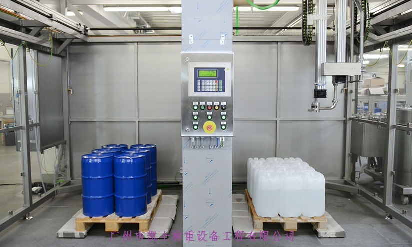
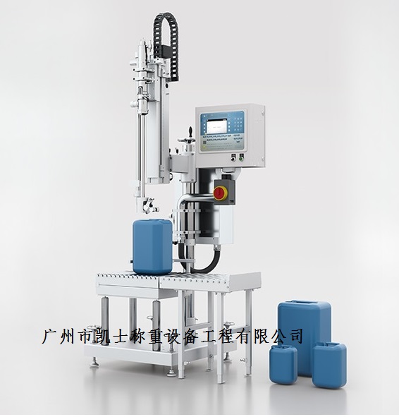
Summary:The automatic filling machine is composed of a variety of unit functions, including raw material storage hoppers, pneumatic control devices, servo motors, filling machinery, frequency converters, electrical control cabinets, electronic scales, etc.; according to the pre-designed weighing program and Quantity value, automatically divide a large amount of bulk liquid into small proportions of weight, the weight of the bulk liquid is transferred to the weighing module, the weighing module will output a signal to the weighing instrument, thus forming liquid filling to achieve complete quantitative control of automatic filling, usually The quantitative process of a single liquid is completed through three actions: fast filling, slow filling and supplementary filling.
1 weighing and filling machine's basic composition and principle of the equipment is mainly composed of the following six parts: the beginning of the barrel filling, driven by the motor of a flat conveyor and a pair of motor-driven by the same service into the barrel screw, the barrel will be separated and synchronized barrels into the barrel into the star wheel; into the barrel into the barrel star wheel by the capping part of the chain drive it will be sent to the empty barrels to fill the machine under the weighing pan, detect the start of the filling in place; the filling is complete to enter the capping area and respectively put the inner cap and seal the inner cap and press the outer cap; finally passed the capping test into the next section E otherwise into the pick barrels area After filling, it enters the capping area and puts the inner cap, seals the inner cap and presses the outer cap respectively; finally, if it passes the testing of capping, it enters the next section; otherwise, it enters the barrel picking area.
2Automatic control system
Liquid filling machine using Siemens SIMATICS7300PUCPLC programming configuration tool STEP7 using SIMATIC software integration to achieve the ease of use of PLC programming configuration and integration with the host group configuration system provides a powerful software platform. PROFIBUS-DP for high-speed data transmission at the field level. The master cyclically reads the inputs from the slaves and cyclically sends the outputs to the slaves. The bus cycle time must be shorter than the master (PLC) program cycle time.
2.1 Composition and configuration of the S7-300 PLC hardware
(1) power supply unit of the AC power supply rectification, filtering, and voltage stabilization, converted into for the PLC's central processor memory and other electronic circuits required for the work of the DC power supply.
(2) CPU unit, including the microprocessor and its control logic, system program memory, user data memory. CPU computing speed, instruction-rich and has a variety of addressing methods.
2.2 Programming software STEP7V5.3
STEP7V5.3 is the software used for SIMATIC design, configuration programming and troubleshooting. Users can write programs and configure hardware in STEP7, and download user programs and hardware configuration information to CPU or upload from CPU to PC. When the program download and debugging are completed, the filling system is ready to perform various automatic tasks.
The performance of the filling system already depends not only on the CPU of the PIC is also affected by the extended environment (i.e. network environment) in which the PIC is located. The PROFIBUS network established for the packaging line of the control system of the fully automatic filling machine is a control network applied to SIMATIC at the unit level and at the field level, applying mixed media transmission technology as well as token and master-slave logic topology, which can be transmitted simultaneously over twisted pair or optical fiber.
2.3 Communication and Configuration of S7-300
First of all, in SIEP7 configuration of two S7-300 station which integrated DP port selected as the master mode, CP342-5 selected as the slave mode. Then, under the hardware list of PROFIBUS-DP, select the CP342-5 from [ConguredStations]/[S7-300CP342-5DP] and drag and drop the CP342-5 selected in the slave hardware configuration to the DP master bus and click the [Connect button to connect the slave to the PROFIBUS network established by the master. Select the slave, in the slave's hardware slot (such as Slotl), insert the appropriate input and output modules, you can also insert the general-purpose (Universalmodule] module, define their own input and output bytes. The system defines a data exchange area of 10 bytes input and 10 bytes output. In this way, the hardware configuration is completed. The PROFIBUS-DP network of the filling machine is a PROFIBUS system consisting of 3 masters and 7 slaves. 3 masters form a token logic ring. When a master station gets a token message, the master station can execute the master work within a certain period of time. During this time, it can communicate with all slaves according to the master-slave communication relationship table, and can also communicate with all masters according to the upper-master communication relationship table. It is a typical distributed master and slave system. This access mechanism, in which the master periodically exchanges data with the slaves in a sequential manner.
3 Online debugging system
The configuration and user program completed on the PC must be downloaded to the PLC and debugged in hardware and software before the automatic control task can be finally realized.
3.1 Establish online connection
SIDP7 provides both offline and online views under the project interface, programming interface, data viewing interface and main interface. The offline view shows the locally stored project content of the PC; the online view shows the actual content in the CPU. Once the PC is connected to the PLC via the programming cable, an online connection can be established in STEP7. In [SIMATICManager], click the Onine button on the toolbar to display the online view.
To debug a PLC system and find faults, you can directly utilize the information from the hardware module itself.The diagnostic mechanism provided by the S7-300 PLC system can help the user to easily find faults and locate the cause of the fault.
3.2.1 Hardware Status Indicators
First of all, the hardware status indicator is the most intuitive interface. there are corresponding indicator lights on the panel of S7PLC modules to indicate the current status of the module. Through the indicator, users can immediately find the error and can initially determine the type of error. Therefore, when the program is downloaded, the first thing to do is to determine the module status from the indicator lights
(1) Power supply module. DC24V: Indicates the status of 24V DC current supply;
(2) CPU module. SF: illuminated when the program is wrong or when the module with diagnostic function is wrong; BATF: illuminated when the battery is wrong; ERCE: illuminated when there is a variable to be forced; RUN: CPU is in the running state; STOP: is in the shutdown state; BF: illuminated when the fieldbus is faulty;
(3) Digital VO module. There is an indicator next to each VO point indicating the value of that bit of VO, and the lamp lights when the IO value is 1.
3.2.2 Diagnostic Buffer
Diagnostics are recognized and logged functions integrated within the S7PLC. There is a diagnostic buffer in the CPU for recording information about events or errors. When an error occurs the system records the event as well as the time of its occurrence in the diagnostic buffer, if the diagnostic buffer is full the oldest information is overwritten. When an error occurs, in addition to recording it in the diagnostic buffer, the corresponding error handling OB may also be called.Using the diagnostic function, the user can find out the error of the CPU or other modules or the error of the user program.
3.3 Testing the program
Logic errors in the program often need to be found by tracking and debugging the program.SIEP7 provides functions for program state detection and tracking and debugging.
3.3.1 Monitoring Program Status
In the LAD program, the monitoring interface displays the status of the signal flow and the values of the variables. Components in a valid state are shown as solid green lines, and components in an invalid state are shown as dashed blue lines. The current value of the variable is displayed at the variable location.
3.3.2 Breakpoint Debugging
With the help of breakpoints, you can test the SIL program in a single step. Whether or not breakpoints are supported, and the number of breakpoints supported, depends on the specific CPU model. To use the breakpoint debugging function, you must first select the CPU operation mode as TestOperation through the menu [Debug][Operation], and the breakpoint debugging screen will appear. The values of the PLC internal registers can be displayed via the menu [View]/[PLCRegister]. Thus the execution of the program can be observed more accurately than with program state detection.
3.4 Realization of system functions
Through the above series of system debugging, basically locate the control part of the hardware and software, and now also need to carry out the whole machine debugging. This step is more critical, related to the performance of the entire filling machine system, the main thing is to affect the filling speed and quality of the entire line.
4 typical fault analysis
4.1 PLC control system to produce false action, dead and other phenomena
In the debugging process, there is a PLC control system to produce false action, dead and other phenomena, every time there is a delay, affecting production, so you have to re-install the driver. After the argumentation and simulation of PLC sequence by foreign experts, it is confirmed that there is no problem with the program, and the main reasons are as follows 2 points:
(1) the operator did not clear the previous file in time after calling the variety of recipe files, resulting in a crash, because this system itself is defective in the development, and it is still tracing the record. At this point, you can only restart, call a new recipe file, a series of parameters in this file must be reset, including the 20 filling nozzle settings, control valves and so on.
(2) from the signal line leads to interference with the PLC control system connected to the various types of signal transmission lines, in addition to the transmission of all kinds of effective information, there will always be external interference signal intrusion. This interference mainly has 2 ways: one is through the transmitter power supply or common signal instrumentation power supply string into the grid interference, which is often ignored; the second is the signal line by the space electromagnetic radiation induced interference, that is, the signal line on the external induction interference, which is very serious. Interference induced by the signal will cause the IO signal work abnormally and the measurement accuracy is greatly reduced, and when serious, will cause component damage. For the poor isolation performance of the system, it will also lead to mutual interference between the signals, resulting in a common ground system bus backflow, resulting in changes in logic data, false operation and crash. PLC control system due to signal-induced interference caused by the number of damage to the IO module is quite serious, which causes a lot of system failures. Rework, found that some of the power and signal lines are very confusing, re-laying cable.
If the PILC system is placed in the RF field, it will receive radiation interference, the impact of which is mainly through two paths: one is directly to the PLC internal radiation, by the circuit inductance of the interference; the second is to the PLC communication within the network of radiation, inductance of the communication line induced by the interference. Radiation interference with the field equipment layout and equipment generated by the size of the electromagnetic field, especially frequency-related, generally through the setting of shielded cables and PLC local shielding and high-voltage relief elements for protection.
4.2 into the barrel screw and the main rotating disk is not synchronized
This is the key to the operation of the entire filling production line is good, into the barrel screw and the host rotation is not synchronized, resulting in the production of three possible results: First, the barrel has been in place, but the filling nozzle parts are not yet in place; Secondly, simply can not be into a complete plastic barrel, may be pinched flat barrel, resulting in a waste of materials; Thirdly, the barrel into the person's speed and filling speed is not synchronized with the speed of filling that is, the speed of the filling and barrel screw does not match.
The reason for this problem is mainly 2 points: (1) the parameters of the frequency converter is not optimal, resulting in the host of the transmission speed between the gears are not synchronized.
(2) host filling area by encoder (encode) accurate positioning encoder and inverter is also communication, through the signal feedback, PID regulation, so that the whole synchronization and positioning is more accurate. However, it turns out that some of the parameters of the servo motor is lost, so that it is memorized to the original parameters out of the wide. Need in the "Monitor" menu "womscrewformat" sub-menu screen into the barrel screw reset, according to the information reset parameter, then will find in the hardware diagnostic menu encoder communication status is also restored to good, and then Optimize the parameters of the inverter, restart and find that everything is normal. However, the operator needs to stop the machine in the non-filling area, if in the filling area, before starting the filling machine, it is necessary to manually find the zero position of the barrel feeding screw.
5 Conclusion
The filling and packaging line after installation, commissioning, after a few months of operation, did not find any faults, running well, basically achieved the desired purpose. Especially stop the rotation of a weighing disk zero this link, automatic weighing is particularly convenient.