
 2020.01.15
Summary:The batching control system can be used for weighing control applications of various reducing feeding equipment. By obtaining changes in material quality at fixed time intervals, the instantaneous flow rate of the material can be calculated.The PID controller uses this flow value to control the feeding amount of the reducing feeding equipment.
Preface
IPA (Isophthalic Acid) is an important ingredient in the production process of PET bottle flakes. In order to achieve continuous production of high quality PET bottle flakes end products, it is required to continuously measure and control IPA with high precision. the amount of IPA added directly affects the quality of the end products. to ensure the efficient and stable operation of the whole process and to ensure accurate metering, it is necessary to optimize and highly automated production process. In order to ensure the efficient and stable operation of the whole process and to ensure accurate dosing, the production process must be optimized and highly automated.
1 Control loop
For continuous process control is generally known as process control or process control, is a continuous regulation of the nature of the control. Regulation is a type of control that specifically refers to the continuous control of a continuously changing object by means of feedback. The flow control loop controls the motor speed by adjusting the inverter output inside the IPA scale to achieve the purpose of keeping the controlled flow within the predetermined flow range, so the PID control loop is used in the system. The inverter output is automatically adjusted according to the desired set value.
2 Measurement principle
INTECONTPLUS reduction type feeding equipment every time after a fixed time interval to read a mass value, by the front and back of the two mass difference to calculate the reduction of each time unit (both instantaneous flow), INTE-CONTPLUS weighing controller will be the actual measured value and the preset flow rate value compared to the same time, while controlling the rotational speed of the screw feeder to regulate the amount of feed. When the mass of material in the hopper of the reduction scale reaches the minimum set value, the charging valve will be opened automatically for cyclic charging operation. In order to ensure correct weighing results, e.g. to avoid the effects of mechanical vibrations, a suitable filter can be selected to filter the weighing signals during their measurement. For this purpose, INTECONTPLUS can set the filter parameters for the level and the weighing value separately.
The measurement process can be realized in 3 modes: mass method mode, volume method mode and volume method synchronization mode.
(1) Mass method mode: The actual value of the feed rate is controlled by a special setpoint. The maximum possible set point corresponds to the rated feed rate. If a value higher than the rated one is entered, message S8 is displayed via the INTECONTPLUS output panel.
(2) Volumetric mode: The material transfer mechanism is controlled in proportion to the setpoint. Changes in the hopper mass have no effect. Under rated conditions, the feed rate corresponds to the infeed setpoint. The set point is limited to 3 times the rated feed rate.
(3) Volumetric Synchronization Mode: The changeover from mass to volumetric mode occurs smoothly. The relationship between the setpoint and the actual value of the feed rate is more precise than in the non-synchronized volumetric mode, and the same is true if the setpoint is changed.
3 System Configuration
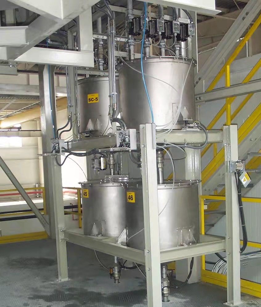
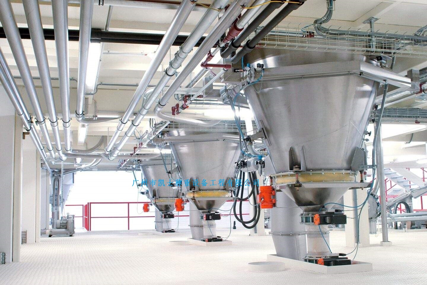
The reduced feeding system is mainly divided into 3 parts: the discharging system, the weighing control system, and the unloading unit. The hopper inlet and pipeline are installed with soft connection to reduce the impact of vibration on the weighing of the material, and the switch butterfly valve is installed in the pipeline to control the addition of raw materials. The main components of the weighing system include: hopper, weighing module, mixing motor, and each component is fixed through the support frame. Discharge through the feed motor assembly, screw, discharge pipe composition. When the material is fed into the hopper through the feeding pipe, the extended hopper can be used as a material buffer and a receiver for the agitator. When the material reaches the set discharge quantity, the discharge screw driven by the feeding motor assembly will act in accordance with the set rotation speed, and the IPA material will be continuously controlled and measured through the discharge pipe.
4 Metering control process
4.1 Unloading weighing
The unloading weighing principle is designed to feed a variety of bulk solids through a reduction feeder, which operates on the principle of controlled material unloading, e.g., the system does not measure the total amount of material fed by the unloading feeder; instead, it measures the reduction in the weighing hopper. In the case of fill weighing, the system measures the added mass. The entire process line is designed to be dust tight and air tight. The filled hopper is weighed with a load cell and the change in mass per unit of time is obtained. This corresponds to the feed rate of the discharge unit. This feed rate can be measured or controlled by a specific set point. If it falls below the minimum hopper level, the hopper is refilled by means of a feed valve switch. The entire unloading and weighing process is divided into 5 steps.
(1) MIN fill signal is output and the hopper is filled. During this phase, the feed rate cannot be measured and the control continues in the controlled mode. The control system displays the setpoint: Measuring system, the feed rate maintains the average of the last measured values.
(2) The message of the ECH0 filling gate is monitored and, if required, an event message is output.
(3) MAX reaches the maximum filling quality and the filling stops.
(4) The feed rate is measured and decremental control is initiated after the return signal from the filler door and the set time TB have elapsed.
(5) The BLOW-0UT filling nozzle blows to remove the residual material.
The filling process can also be controlled temporarily (pulse filling) but is stopped as soon as the MAX value is reached.
4.2 Fill weighing
The filling weighing principle is the opposite of the unloading weighing. Measurement and control take place while the hopper is being filled. There are speed-controlled feed units (e.g. feed screws) and amplitude-controlled feed units. both types require the presence of an external power controller for armature voltage or amplitude, as well as special control circuits. The actual feed rate is compared to the set value, the difference is transmitted to the RP and the controller continuously changes the feed rate of the discharge unit until the actual value is equal to the set value. In order to speed up the calibration of the set value, the controller is mediated by additional pre-control.
4.3 Automatic disturbance eliminator (DAE)
Throughout the weighing and metering process, 2 types of disturbances are generated for various reasons, i.e. unloading disturbances and measuring disturbances.
(1) unloading interference. Produced by the unevenness of the material, material changes and unloading unit of the nonlinear and so on.
(2) Measurement interference. Produced by the vibration of the building, the wind, weighing contacts and so on.
The first type of interference exists in both the measurement signal and the flow process, and the second type exists only in the measurement signal. This type of interference must not be fed into the evaluation and control of measured values. In view of the fact that there are these types of interferences, a special eliminator has been improved to operate on fuzzy logic principles. The system categorizes the disturbances and determines the required measurement and control mediators. Differential filters and control parameters are calibrated as a function of the predicted disturbances to ensure that only an uncertain fraction is fed into the measurement and control. The automatic interference eliminator allows the material to be refilled without changing the mode of operation. If the eliminator is properly calibrated, refilling should proceed smoothly. Special settings can also be made to achieve more complex filling sequences. If the volumetric feed rate is a function of hopper level, the controller must continuously recalibrate the unloading unit during the mass law condition. In order to simulate the state during filling, the unloading unit control amplitude is adjusted to the hopper level during this phase. This increases the feed accuracy during the filling phase and ensures a smooth transition to the mass law state.
4.4 Linearization control
Vibratory feeders over their full power range are not linear but exhibit a progressive feed rate to amplitude. Linearization ensures control accuracy over the entire setting range and prevents downshoots and over-radialization at the set point step.
5 System Operation
The automatic dosage system is realized by means of the INTECONTPLUS controller, with an operating panel that allows the display and setting of various parameters.
The program controls the entire weighing process and configures the switch input signals including the start button, shutdown button, bucket door status and other detection signals. The switch outputs are control signals (e.g. thickness feed solenoid valve, exhaust solenoid valve, bag clamping, etc.), weight indicator, alarm output signals. The digital channel receives the weighing module weight input signals. One of the hopper scale closure and clamp back clamping tests is proximity switching, where the buffer zone door, hopper scale and clamp back cover are actuated and controlled by solenoid valves. Ideally, the large supply is the small supply and together they accomplish 95% of the rated weight value in a very short period of time. Then the big supply stops and the small supply produces another 5% 10% of the rated weight value, taking up a much longer period of time. In actual production, the weight and time parameters of these two segments must be constantly adjusted to the situation in order to achieve the optimum.
6 System Advantages
Since the whole dosage control system has been put into operation, the measurement is accurate and well controlled, it is possible to manage the parameters and set the preset values of the weighing system directly through the INTECONTPLUS control, it is possible to set the parameters of the quantitative feeding conveniently at a remote location, it is possible to obtain the use of the characteristic curves automatically, it is possible to realize a simple remote adjustment of the metering parameters. The main advantages are:
(1) Improvement of batch dosing metering accuracy without interference from external factors (e.g. mechanical vibration, etc.).
(2) Acquire and display material level and material mass value respectively, which can be applied to different kinds of solid powder media metering control with different density.
(3) Easily integrated into the INTECONTPLUS system, enabling the perfect combination of weighing and control.
(4) Easy to install and read the weighing data and set up the weighing system via various communication methods, e.g. simple integration into the weighing system via a modem or Ethernet communication module.
(5) The weighing data is fed directly into the DCS system via the backplane, saving the communication link between the weighing equipment and the DCS system and reducing costs; at the same time, it realizes the high-speed remote control function.


