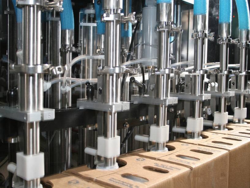


Summary:The batching system works through the coordination of industrial computers, PLCs and frequency converters. RS232 is connected to the industrial control host. The industrial control host located in the central control room is responsible for recording the weighing results, displaying the weighing data, and controlling the start and stop of the batching process through the control circuit.
1 Introduction
In the polymer materials production industry, dosing is usually the raw materials in a certain proportion of uniformly mixed together to form a new material, so dosing is an important part of the production of such industries. In the production process, a variety of raw materials to be strictly proportional to the uniform mix, it must rely on the dosage to complete, the factory generally use two methods, the first method of manual weighing, and then into the proportion of the various raw materials into the dosage equipment at the same time mixing. The other method is automatic weighing and mixing. Because many raw materials are powder or granule, when manually batching, human body is easy to inhale dust and other debris, resulting in occupational diseases, increasing the production risk and labor cost, at the same time, there are many varieties of ingredients, the quantity is huge, so it is difficult to manually batching on-site management, it is easy to misallocation, not only the quality is difficult to guarantee, but also increase the management cost. In order to ensure product quality and improve production efficiency, it is required to use accurate and reliable automatic dosage system. Based on PLC, industrial control machine and weighing instrument feeding system in the existing system of polymer materials, workers firstly transport the materials to the weighing workshop, after weighing, then the materials will be manually sent to the batching equipment for batching, the weighing workshop uses the weighing instrument for measurement, which is connected to the industrial control mainframe through the RS232 port, and the industrial control mainframe, located in the central control room, is responsible for recording the weighing results and displaying the weighing data, and the controller can display the weighing data in the central control room. At the same time, the controller can manually control the starting and stopping of the batching process through the control circuit in the central control room. This method is inefficient, at the same time, the host computer is running a DOS program developed in C language, poor scalability, human-computer interaction is difficult, and can not complete all the requirements of automatic batching. In order to improve productivity and reduce cost, a fully automatic feeding system is needed. The master-slave structure is adopted, with the industrial computer as the upper host and Siemens PLC, frequency converter and weighing instrument as the lower slave. The host is in the dominant position to realize the communication management and control of the slaves. The RS-232 asynchronous communication port of the ICP is connected to the PLC after level conversion to form a physical channel for the communication between the upper and lower units; another RS-232 port of the host is connected to the communication port of the weighing instrument to form the second physical channel. The upper computer adopts polling method to communicate with the slaves one by one. The upper computer transmits the results of the task planning to the product and application PLCs. During the control process by the PLCs, the upper computer uses the upper computer connection commands to monitor the operation status and data area contents of the lower computer, and the internal status of the PLCs, as well as the real-time data of the weighing instruments, are displayed on the upper computer. In general, the automatic batching system has the following functions:
①Full-automatic dosage, after setting the formula, the automatic dosage system weighs and dosages according to the formula automatically without operator intervention;
② With report function, it can produce daily report, real-time report, monthly report and annual report;
③ Dynamic increase and modification of reports, the automatic dosage system gives the technician or operator the right to modify and increase the formula by setting the authority, and at the same time records the date and operator number of the modification;
④ Power failure recovery function, the automatic batching system can recover the measurement records before power failure in case of sudden power failure;
⑤ LAN sharing function, the host can share the data in the LAN, which is convenient for the workshop supervisor to know the progress of the project and other situations.
2 Composition of automatic batching system
The whole automatic batching machine is composed of industrial control machine, PLC, weighing instrument, frequency converter, vibration motor, mixer, weighing module, conveyor belt and other parts. The upper computer provides human-computer interaction interface, completes the control information input, data management, data display, storage, statistics and reports, etc. The upper computer adopts IPC810 industrial computer, and its main work is as follows: the industrial control host firstly reads a certain number of formula according to the operator's instruction, and then, according to the proportion of the ingredients in the formula and the sequence of the ingredients, the PLC sends out the instruction to start the batching, which enables the PLC to start the specific batching. Then, according to the proportion and sequence of the ingredients in the recipe, PLC sends a command to start batching, which enables PLC to start a specific frequency converter. In the process of batching, the host computer of industrial control reads the status words of PLC in real time by polling, on one hand, to understand the operation status of PLC and PLC subordinate equipments; on the other hand, it reads the weighing data of the weighing instrument installed on the batching equipment in real time, and according to the strategy of batching, the host computer sends out the instruction of stopping batching to the PLC when the weighing is close to the set value of the recipe. When all the materials on a recipe are dosed, the whole dosage, waiting for the operator's instructions. During the operation of the automatic batching system, PLC communicates with the host computer in real time, so as to ensure the consistency between the data displayed on the interface and the actual data on the site, and the operation commands and setting parameters issued by the operator on the host computer can be sent to the PLC in real time, and the main work of the PLC is:
①Receive the commands sent by the upper computer and control the start, stop, fast and slow of the vibration motor through the frequency converter;
② Write the running status of the frequency converter into the memory data area in real time for the industrial control machine to read;
③ Prepare its own various states in the form of status words, totaling the industrial control machine to read in real time.
3 control strategy and batching process
By analyzing the characteristics of the dosage process, the dosage process has the following characteristics:
(1) The controlled object is a one-way irreversible automatic batching system. There is no way for the raw materials to return to the conveyor belt from the dosage equipment.
(2) It has obvious time lag. When the dosage reaches the set value, PLC controls the motor to stop transmitting the raw materials, at this time the conveyor belt has part of the raw materials can not be recovered, so the automatic dosage system has an obvious time lag.
(3) The controlled characteristic is switching. Automatic batching system start, stop control, etc. are switching quantities.
(4) The system is linear within the normal working area. Consider adopting control strategies such as fast, slow, and stop dosing command in advance, and at the same time, utilize PLC's interlocking technology to ensure the smooth progress of dosage. After the system starts, the industrial control machine sends a signal to PLC to start feeding, PLC controls the frequency converter to drive the motor for fast feeding, at the same time, the industrial control host continuously reads the weighing data of the weighing instrument through the serial port, when the weight value is close to the set value, the industrial control host sends a control instruction to PLC to stop feeding, at this time, PLC controls the frequency converter to carry on the slow feeding, by estimating the raw material on the conveyor mechanism in advance By estimating the residue of raw materials on the conveyor in advance, when the difference between the set value and the actual feeding and the residue of raw materials on the conveyor are quite the same, PLC really sends out a stop command, which is executed by the frequency converter, thus controlling the motor to stop, and after stopping, there is no residue of raw materials on the conveyor, and the accuracy of the dosage is in accordance with the requirements.
4 industrial control host software design mainly accomplishes the following tasks:
(1) Provide animation display of batching process.
(2) Issue control instruction to PLC and read the operation status of PLC.
(3) Read the weighing signal on the weighing instrument and display the weighing value on the monitor, and send commands to PLC according to the weighing data.
(4) Database and report, save dosage data and print report.
(5) Addition and modification of formula.
(6) Other functions such as dosage fault auxiliary alarm.
4 dosage software interface design
The upper industrial control machine using configuration software to design the human-machine interface, industrial control configuration software is actually a kind of software development platform that can be developed by users according to their needs. According to the process requirements on the platform to monitor the entire automatic feeding system to develop a friendly human-machine interface, the operator through the interface can interact with the field equipment in real time. The software is HMI/SCADA industrial automation configuration software, providing a highly integrated, visualized development environment. The software has some of the following features:
(1) a variety of communication functions. Configuration software supports the following communication functions:
(1) support RS232, RS422, RS485 and other serial communications, and support for radio, telephone dialing, telephone polling dialing and other methods.
2) Ethernet communication supports both wired Ethernet and wireless Ethernet.
(3) All device drivers support mobile network standards such as GPRS, CDMA and GSM.
(2) Convenient development system. Rich components and controls constitute a powerful HMI development system; Enhanced transition color and progressive color function, which fundamentally solves the problem that many similar software seriously affects the screen refresh speed and the operation efficiency of the automatic dosage system when transition color and progressive color are overused; More flexible and diversified vector sub-diagrams make it faster to make project screens; Provide object-oriented programming, built-in indirect variables, intermediate variables, database variables, and support for customized functions. It provides object-oriented programming mode with built-in indirect variables, intermediate variables and database variables, and supports customized functions and customized menus.
(3) Openness. The openness of the configuration software is shown in the following aspects:
(1) Support Excel to access the database in the form of VBA.
(2) software for the open architecture, full support for DDE, OPC, ODBC/SQL, ActiveX, DNA standards. OLE, COM/DCOM, dynamic link libraries and other forms of external access interfaces to facilitate the use of a variety of commonly used development tools (eg: VC++, VB, etc.) for deep secondary development.
(3) Configuration software I/O driver architecture for the open structure, the interface part of the source code is completely open, the user can develop their own new driver.
(4) Database function. The configuration software has a built-in real-time database, and the real-time database has a variety of built-in function blocks to complete the data processing and storage, which can realize the totalization, statistics, control, linearization and other functions.
(5) Support a variety of devices and buses. It supports PLCs, regulators, intelligent meters, intelligent terminals and intelligent modules produced by most of the famous manufacturers at home and abroad; in addition, it also supports standard field buses such as Profibus, Can, LonWorks and Modbus.
5 System I/O points
The configuration software uses real-time database points to represent I/O points. After analyzing, the system needs three I/O points, two digital control points are used to control the starting and stopping of the motor through PLC, so the data link selection of these two points are the two digital input and output channels of PLC respectively. One analog point is used to represent the real-time data read from the weighing instrument, so the data link of this point is the measured value of the weighing instrument.
6 Communication Program Design
The communication program design mainly contains three parts, the first part is the communication between the host and PLC; the second part is the communication between the host and the weighing instrument; and the third part is the communication between PLC and inverter.
7 Host and PLC communication
The configuration software generally has built-in drivers for mainstream PLCs, first of all, a new PLC virtual device is created in the configuration software, the model of the virtual device must be the same as the model of the real PLC used, if you can't find the required PLC model in the configuration software, you can entrust the software manufacturer to develop a new PLC driver of the model free of charge. The virtual device is used to map the real device. Here, the PLC we use is SimensS7-300, and the host computer is set to communicate with the PLC through serial port 1.
8 Communication between the host computer and the weighing instrument
The weighing instrument is commissioned to develop a driver for the instrument in order to communicate well with the configuration software. First we select a device type we need from the driver list of the configuration software, and for that type, we create a virtual device to map the real weighing instrument, and then we set the communication port and communication protocol between the instrument and the computer.
8Communication between PLC and inverter
Since there are many kinds of raw materials in the batching plant, we set up several conveyor belts for the convenience of batching, so one PLC of the system needs to be linked to several inverters. For this reason we use Profibus bus for communication between PLC and frequency converter, insert the special Profibus communication module into the frequency converter, and set the slave address of the frequency converter, and then access to the PLC through the Profibus connector, PLC through the programming, to realize the transmission and reception of telegrams to this frequency converter, and send the control word to the frequency converter. CPU315-2DP acts as the Profibus master, and each inverter communicating with the master can be regarded as a Profibus slave. When communicating, the master station selects the slave station to transmit data according to the address characters in the communication message. The station itself cannot send data on its own initiative, and there is no direct transmission of information between the individual slaves.The main communication between the PLC and the inverter involves two main concepts. The first is the data telegram and the second is the control and status characters. (1) Communication telegrams. Each message starts with the character STX, followed by the length description LGE and the address byte ADR, and then the adopted data characters, and the message ends with the check character BCC of the data block, and the main fields are explained as follows: the STX area is a one-byte ASCII character (02hex), which indicates the beginning of a piece of information. the LGE area is a byte that specifies the number of bytes that will follow in this one piece of information. The ADR area is a byte that is the address of the slave node (i.e., the inverter).The BCC area is a checksum of one byte in length that is used to check whether this message is valid. It is the result of the "different-or" operation of all the bytes in front of BCC in the message. If the result of the checksum operation indicates that the message received by the inverter is invalid, it will discard the message.
(2) Control word and status word. PLC can read and write the parameter value of the inverter through the PKW area of the inverter, so as to change or understand the working status of the inverter. In this automatic dosage system, PLC reads out the data of the zone and puts it in a specific data area for querying by the industrial control machine, and the query result is displayed on the industrial control machine.
9 CONCLUSION
This automatic dosage system completes the required automatic dosage task through the coordinated work of industrial control machine, PLC and frequency converter. Since the automatic dosage system is put into use, it dosages more than 100 tons per day and completes about 10 formulas, which not only displays the working condition in real time, but also provides the functions of formulas modification and increase, etc.; The actual operation shows that the dosage mixer is stable and reliable, and the man-machine interface is beautiful and easy to operate. The actual operation shows that the batching and mixing machine is stable and reliable, and the man-machine interface is beautiful and easy to operate. We can analyze and conclude that: transformer operating temperature in May to August more than 80 ℃ days up to 91.3%. This shows that 80℃ should be an important temperature node for transformer operation temperature control. Therefore, we FCB-2R4 type temperature control system of polymer action temperature value made a new setting: fan starting temperature is set to 80 ℃, stopping temperature is set to 70 ℃, over-temperature alarm temperature is set to 110 ℃, over-temperature tripping temperature is set to 140 ℃. Such settings can minimize the impact of temperature on the transformer.