2020.02.20


Summary:The weight of the material on the weighing section of the weighing batching system is converted by the weighing module to obtain an electrical signal proportional to the weight. After isolation by the photoelectric coupler, the output frequency of the frequency converter is controlled, thereby changing the motor speed. The accuracy of batching of industrial computer is ensured.
1 Control strategy for feeding process
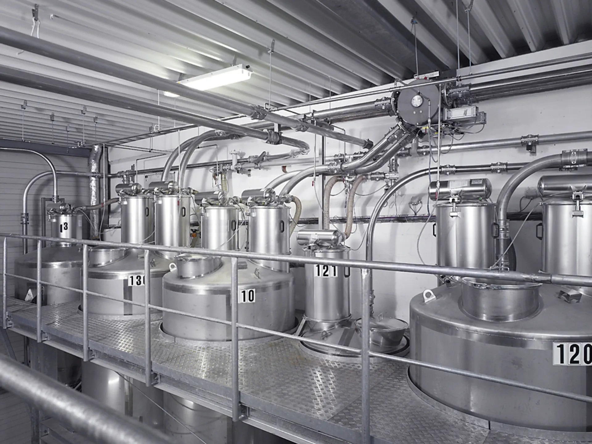
The structure of the AC reactor feeding and dosing system of this plant consists of 8 high level bins, valves, vibration material motor, an explosion-proof electronic weighbridge and weighing trolley, as well as a set of position detection devices.
The feeding process includes five stages: feeding waiting, weighing, discharging waiting, discharging and returning. In the charging waiting stage, the trolley stops the reaction tank after the charging port position waiting for the control command. In the weighing stage, according to the feeding parameters input by the operator, the trolley automatically walks to the specified material position, locks the position when it is in place, and the vibration motor of the silo opens to vibrate the material. By constantly collecting the amount of feed, when the dosing set value reaches a set amount of advance stop, here the amount of advance can be calculated by turning off the motor to stop the vibration of the time or based on experience. When the added material is solvent (such as resin, polyurethane, etc.), it immediately enters the discharging stage, otherwise it enters the discharging waiting stage, and the trolley stops at the original place and waits for the discharging order to come. In the discharging stage, according to the type of material to be added, the feeding trolley automatically walks to the feeding port in front of the reaction tank or the feeding port after the reaction tank, opens the feeding valve after the trolley is in place, and the trolley automatically stops at the waiting position for feeding (i.e., after the feeding port of the reaction tank) after the completion of discharging and waits for the next feeding. When the feeding error occurs or there is material left in the trolley, it will carry out the return program.
Feeding real-time control process by a Siemens 115U PLC controller to complete, while using the upper PC for communication, in the upper computer to complete the feeding parameters set, data management, statistical reports, printing and other functions.
Considering the importance and safety and reliability of the feeding system, the original manual feeding operation means are still retained, thus the automatic feeding and dosing system has two working modes: automatic control and manual operation. In the automatic mode, the operator only needs to input a small amount of information such as the type (bin number) and weight of the dosage, and the PLC dosage system automatically completes the whole process of weighing and dosage. In the manual mode, it is completely by the operator to complete manually.
2 Dosing hardware composition
The hardware structure of the dosing system mainly consists of UPS, PC, printer, serial conversion card and PLC, electronic scales, valves, motors, position detection devices and other actuators. The upper computer through the RS232/RS485 serial conversion card and PLC communication, high-speed, stable and accurate data transmission.
For security reasons, two PCs are set up to be powered by UPS and work in hot backup mode, so that the system can still run reliably if any one of the PCs fails. All the field equipment control work is completed by the PLC, the host computer is only responsible for providing human-computer interface, dosing data input and display, storage, statistics and report printing. When the two upper computer fails at the same time, the PLC automatically switches to manual operation mode, which can still ensure the normal production. At the same time, the PLC is equipped with a battery, which can save all the dosage system setup parameters and field status data. During the operation of the dosage system, PLC has been real-time communication with the host computer to ensure the consistency of the data displayed on the interface with the actual data on the scene, and the operating commands and setting parameters issued by the operator on the host computer can be sent to the PLC in real time for execution.
3 dosing system software design
Automatic feeding dosage system software includes the host computer and PLC two parts. These two parts are written separately, and establish the communication protocol between each other. The host computer and PLC have their own function modules, the host computer through the communication subroutine, PLC through the communication interrupt subroutine through the RS232/RS485 serial bus converter card to establish a communication link between each other, the data in the form of frames in the transfer between the two.
In order to take into account the communication speed and execution efficiency, there are two types of data communication formats between the upper PC and the PLC, i.e., query frame and control frame, where the query frame requires only one identification byte, and the control frame, which contains control information, requires 128 bytes or more. These two types of data frames are described as follows:
① Control frame ---- more than one byte. The first byte is the identifier, the value is 0. The following bytes contain all the control information, such as material level number, material weight, discharge port selection, lead time, whether to calibrate the scale or not, whether to pause or not, and so on.
② The query frame ---- contains only one identifier byte with the value of 1. The handshaking mechanism between the host computer and PLC is as follows:
PLC always receives the data frame from the host computer in interrupt mode. If it is a query frame it immediately transmits the current control information to the upper computer; if it is a control frame, it waits for the execution to be completed and then sends back data to the upper computer. If the communication fails, the PLC enters the offline working state, and the host computer is responsible for restoring the communication.
In order to maintain the consistency of parameter setting and control state between the host computer and PLC, PLC is responsible for saving all the dosage setting parameters and field state data. When the host computer is first turned on, it sends a query frame to get the actual status data of the current PLC (including the field data and the system data previously set by the operator). Then the host computer sends commands to PLC all the time: if there is a control action, it sends a control frame; if not, it sends a query frame. Under normal circumstances, the PLC receives the query frame from the host computer and immediately sends a data response frame with the same format to the host computer. Since the PLC has been executing the main program in a loop, while handling the communication with the upper computer in an interrupt mode, and this interrupt has the highest priority, thus ensuring that the control commands of the upper computer can be responded to in a timely manner.
3.1 `Upper computer software
The upper computer is divided into main module, dosing parameter setting, process screen, statistical report, communication and other modules. It is mainly for feeding parameter input, process screen display, statistical report, printing and database generation and maintenance. In order to real-time, high-speed and stable communication between the host computer and PLC. The upper computer sets up a separate communication subroutine, which runs independently in the background, and the data exchange between the main program and the communication subroutine is realized through the pipeline. The upper computer software is realized by VB6.0 with good graphical user interface on Win95.
3.2 Main Program
The main program carries out unified management for each module and is responsible for the initialization of the whole system, setting of charging parameters, updating of data on the process simulation screen and statistical reports, printing, generation and maintenance of the database, and so on.
In order to make the process simulation screen intuitive and simple, not easy to make mistakes. The interface design adopts the method of integrating the state display and operation key. That is, the control on the screen has been real-time display of the actual state of the corresponding object, while the operator can click on the mouse to directly select the material and enter the material weight and other parameters, and the data uploaded by the PLC for the refresh of the screen state.
In the database management, in order to facilitate statistical analysis and reporting by workshop or operation area personnel, three types of forms (i.e., daily, monthly and yearly) are designed. And the tables are named by date, such as: Day19990903.db, Month199909.db, Year1999.db, etc.. At the same time, in order to facilitate the labor competition and production index comparison between shifts, the database management has set up a system of signing in for shift change of operators, for which two types of forms (i.e., monthly and yearly statements) have been set up, and the production of each shift is recorded in the respective monthly and yearly statements, which are named A199909.db, A1999.db, B199909.db, B1999.db, B1999.db, and B1999.db, etc., in order to facilitate the comparison of labor competition and production index between shifts. B1999.db...... and so on. Such a database design facilitates horizontal comparison between shifts, and is also conducive to production reports and statistical analysis of the entire electroreactor production.
3.3 Inter-process communication and synchronization
The dosing control system uses the anonymous pipeline provided by WIN95 in the software in order to realize the communication between processes. First of all by calling the WIN32 API CreatePipe function to establish the pipe. This function returns two handles, one for reading and one for writing. In the main process, after the establishment of the pipe, you need to pass the handle to the communication sub-process, the sub-process can read the data in the pipe. Since anonymous pipes can only pass data in one direction, in order to realize the communication sub-process to pass data to the main process, in the sub-process also need to create a pipe, and pass the read handle to the main process. The easiest way to accomplish this operation is to use the standard input and standard output handles that each program uses by default. By setting the standard handles in the master process, which the child process inherits from the master process, two-way communication between the master process and the communicating child process can be achieved by setting the handle of the pipeline created by the child process to the standard handle and having the master process inherit it. When a process writes data to the pipe, the write operation returns immediately, thus ensuring real-time high-speed data transfer between the master process and the communicating subprocesses. Due to the unidirectional nature of Windows anonymous pipeline data transfer, it ensures that no conflict arises between the master process and the communication sub-processes, and well handles the synchronization problem of inter-process communication.
3.4 Communication subroutine
The communication subroutine is the link between the upper PC and the PLC. It is responsible for ensuring that setting data and control commands from the user of the main process are sent to the PLC in a timely manner, and then refreshing the communication pipeline according to the data sent back from the PLC.
Communication between the communication subroutine and the PLC using serial communication, commonly used serial communication methods are two: one is to call the Windows API function, its programming is cumbersome, the use of more complex; the other is to use the VB6.0 serial communication control (i.e., Windows MSCOMM32.OCX6.0), the control to achieve asynchronous communication in two ways: that is, query mode The control realizes asynchronous communication in two ways: query and event-driven. Considering the reliability requirements of real-time control, event-driven communication is chosen. This is a very powerful serial communication method, which can detect the occurrence of communication events at any time to ensure the high reliability of communication.
4 Conclusion
This weighing and batching system between the upper computer and PLC using strict algorithmic control, pipeline communication technology, reducing the amount of system communication, improve communication speed and efficiency. The upper computer image intuitive process simulation drawing.