2025.05.01


Summary:Dosing control system for PVC production process, using programmable controllers and industrial control computers combined with distributed dosage system, that is, IPC-PLC DCS. the use of PID control algorithms to achieve high precision, high reliability control of the PVC mixing system, to achieve the automation of the production of PVC mixing and management of scientific, and thus improve the competitiveness of enterprises.
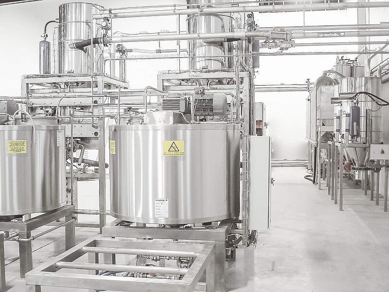
1.Introduction of PVC microcomputer dosage control system for mixing
According to the PVC production control process environment and process control requirements, after research, analysis and determination of the PVC production process microcomputer feeding system selected IPC-PLCDCS system. pc-PLCDCS system for the upper and lower two-layer step structure. Control of the upper computer using two industrial control computers, due to the system detection points, and taking into account the requirements of the system upgrade, the lower computer using a large PLC. monitoring software, including the upper unit configuration control software, communication software, and the lower machine ladder programming software. The system has a high performance-price ratio; the system is open and easy to upgrade; the system has high control accuracy and excellent performance; the system has high measurement accuracy, fast speed and reliable operation, which fully meets the technical requirements of PVC production process.
2. Upper computer software system design
The upper computer can directly set and modify the control parameters of each mixer, real-time monitoring of the lower computer, displaying the temperature, formula and other data, as well as solenoid valves, motor status; in addition, the temperature and other data must be recorded for historical inquiries, generate reports. And for a variety of alarm conditions that can be dealt with during the operation of the system, the host computer must be automatically detected and pop-up alarm window, the alarm window displays the name of the alarm variable, the value of the variable when the alarm, the cause of the alarm, the state of the description of a series of information, and at the same time, in the response of the host computer screen on the corresponding position of the alarm light indicator. The system is composed of the following six functional modules:
Data Acquisition and Transmission Module: Data acquisition is realized by the measuring elements of the field metering module in the network, and data transmission depends on the network connection between the PLC and the host computer. Acquisition and transmission module to achieve the function of the field equipment collected by the equipment operation information, and then sent to the host computer port, in accordance with certain network communication protocols decoded and sent to the PC, the software will be sent to the data display and secondary processing.
Unit information monitoring module: this module will feed into the dosage system of various equipment operating status for the screen display, trying to be the most simple and direct way to the field unit information on the monitor real-time monitoring. This part contains real-time analog quantity, system operation status graph, alarm and time screen, record screen, and unit information secondary screen.
Alarm and Processing Module: This module handles the abnormal condition information of each unit and the connected equipment of the unit, and the output of the processed information is available in three ways: display output, printer output and analog screen output. There are secondary processing and tracing functions for the alarm information.
Control and set parameter value module: This module is the upper computer to the field unit to send information and output module, it provides control functions. Event Record and Processing Module: This module provides the historical record of the changes of the on-site equipment for the operator in analyzing and judging the operation of the system, and provides the original reference number for the next operation of the system. User rights management module: According to different users to give different levels of management rights.
The upper computer human-machine interface is mainly the operating status of the screen display, trying to the most simple and direct way to the field unit information in the display of real-time monitoring, the part contains real-time analog quantity, the system operating status chart, alarm and time screen.
3. Lower computer software system design
Since the weighing accuracy of main material scale and auxiliary material scale is required to be high, the proportional-integral-derivative (PID) control algorithm is used in the dosage control system. In this system, the PLC as the core of the dosage control system is designed to continuously control multiple control loops, which is a time-discrete dosage control system. A frequency converter is used in the system to control the rotational speed of the screw feeder motor, so the incremental PID control algorithm is used.
The whole production process of PVC blending is mainly divided into feeding section, batching section, mixing section and storage section. According to the system process characteristics, the lower computer program includes the following parts:
System initialization subroutine: initialize the system, read the control parameters of PVC production process, firstly, carry out the state detection of the silo, detect that the silo is not empty, then carry out the checking of the current value of the main material scale and the auxiliary material scale, and carry out the dosage process under the condition that the scale value is relative to zero, the end of the dosage will be carried out in the mixing process, and finally, the material will be discharged, and the materials will be put into the storage silo.
Main material loading system control subroutine: the loading system control subroutine mainly completes the function of loading the main material bin, the system detects the position switch of the lower material level of the main material bin in real time, when it is valid, the system gives the indication of lack of material, and automatically opens the loading fan, and sends the main material to the main material bin from the dumping station of the main material by using the aerodynamic force until the system detects that the loading level is valid, then it will shut down the loading fan and the dust-removing fan sequentially, and turn on the pulse blowing for 5 minutes to clean up the material, and then it will be blown away. Pulse blowing for 5 minutes to clean up the dust caused by feeding.
Auxiliary material feeding system control subroutine: the auxiliary material system control subroutine mainly completes the function of auxiliary material bin feeding, when the system detects that the material level meter switch of any auxiliary material bin is valid, the system will give the indication of lack of material, notify to throw auxiliary material, turn on the feeding blower, turn off the door of the auxiliary material, cut off the corresponding position switch, turn off the feeding blower and the dust removing blower according to the sequence and turn on the pulse blowing for 5 minutes, clean the dust caused by the feeding. The dust caused by feeding will be cleaned up by turning on the pulse blowing for 5 minutes.
Feeding system control subroutine: in the batching process, according to the characteristics of PVC batching equipment, using dynamic control methods, in the process of batching the actual value of the batching scale must be real-time with the formula set the weighing value of raw materials.
Mixing system control subroutine: mixing system control subroutine to achieve the auxiliary materials bin after the material mixing, the system must be configured before mixing the control parameters used.
Storage system control subroutine: storage system control subroutine to achieve the final material storage function, the system real-time detection of the storage bin on the material level is valid to meet the upper material level is invalid, the transition bin on the material level meter is valid, start the corresponding feeding fan, when the detection of the transition bin under the material level meter is valid, the two-minute delay, turn off the fan, open the pulse blowing, to remove the dust.
Weighing meter value reading subroutine: it is mainly used for reading the weighing meter and completing the simple data processing function. Alarm subroutine: When any of the following situations occurs, it will give an alarm and stop the related equipment: the cover of the hot/cold machine is not closed, the protection switch of each motor is effective, and the material level meter on the storage bin is effective. Give sound and light prompts when any bin is empty or full.
Manual control subroutine: when the system fails, use this program, at this time, the upper and lower computer only play a monitoring function of the system, can not operate the system, the system has a manual, automatic control buttons.
4. System debugging
4.1 Lower computer programming
Lower machine programming using OMRON's professional ladder programming software CX-ProgrammerV3.10, and refer to the OMRON programmable controller C200HX/C200HG/C200HE programming manual content. According to the requirements of PVC mixing production process and program flow chart to write the program segments, the written program will be transmitted to the PLC, in the CX-Programmer monitoring mode for debugging and modification, until it meets the requirements, when the upper computer program is written, but also to carry out the upper computer, the lower computer joint debugging, when there are conflicts and contradictions, should be appropriate modification of the upper computer or the lower computer program. When there are contradictions and conflicts, the upper or lower computer program should be modified appropriately. Part of the program segment description: 4.1.1 single-button start/stop logic implementation in this design many times using this program mode, now the system power on/off button as an example to illustrate, the statement table is as follows:
LD 4.12
DIFU HR9.15
LD HR9.15
OUT TRO
LD TRO
AND HRO.00
KEEP HRO.O0
4.1.2 Realization of the program of the mixing process section The statement table and description of this program section are as follows:
LD HR2.08
ANDNOT TIMO13
TIM 012 #0600
LD TIMO12
TIM 013 #0001
LD TIMO12
LDNOT HR2.08
CNT 014 DM31
LD HR2.O8
AND CNTO14
OUT HR2.11
4.2 PC programming
The upper computer program mainly realizes the real-time monitoring and control of the lower computer and the human-computer interaction interface. Industrial configuration software is the best choice to realize PLC monitoring, and the latest version of Chinese general industrial configuration software MCGS6.2 is selected for this system. Appropriate components are selected from the object component library of MCGS and placed in the corresponding position of the graphical interface to represent the auxiliary material warehouse, main material warehouse, dumping station, hot mixer, cold mixer, motors, valves, fans and other devices. Use MCGS's flow block component to represent the pipeline on site. Adjust the relative position and size of each element to make the whole picture more harmonious. After that, the equipment configuration is set, and the data object is defined. The data object is directly related to the bit address or word address of the IR area, HR area, DM area and TR area of PLC, and the animation connection between the animation elements of the upper computer and the data object is established. When the data collected by the lower computer changes, the related animation elements of the graphic interface of the upper computer will be "moved" to simulate the running state of the site. Various components and script functions provided by MCGS are used to realize alarm processing, real-time data display, historical data browsing, recipe management, system parameter setting, user management, real-time curve, historical curve, window calling, system menu and other functions.
4.3 debugging
After the upper and lower computer programs are written, they enter the joint testing stage, and the programs to be tested are tested by CX-Programmer and MCGS operation modes. Give different input signals to PLC according to the process flow, or click the corresponding button on the upper computer to simulate the scene, check the output signal indicator light of PLC and the corresponding display state of the upper computer, and compare it with the theoretical results. If different results are found, it means that there is something wrong with the program, and the errors should be checked, corrected one by one, and then tested until all the tests pass.