
 2020.08.18
Summary:The automatic batching system adopts fieldbus control & distributed I/O structure to realize the functions of thermal oil supply and batching supply to the reactor, as well as the functions of vibrating, measuring, unloading and dust removal.At the same time, it accepts the control instructions from the master station, measures relevant setting values, coordinates batching instructions, and makes corresponding responses.
I. Fieldbus control concept
Automatic dosage system for the reactor weighing using the traditional cloth I / O structure, for thermal oil tanks, gas purification system, the use of field bus way. In this way the above three feeding system according to the dosage machine in the monomer for the field of small PLC control and electrical control, by the field of PLC to complete the monomer function control and electrical operation, and by the upper level of PLC to realize the production process technology collaboration control. The on-site PLC sub-batching system and the upper level PLC are connected through communication.
In practical terms, the mixer is not a complete fieldbus approach, but draws on the concept of fieldbus field intelligent control, so it is called fieldbus control.
Second, the proposed basis for the program and reliability analysis:
This way of proposing a show in the field equipment to get the characteristics of the basis proposed. Reactor automation is mainly a reactor weighing, reaction tanks, frame tank dosing, bags, thermal oil reaction tank and other system components. In the above feeding system, from the point of view of equipment function and distribution, can be divided into two categories:
1, suitable for distributed I / O structure of the equipment
The first category is the dosage system composed of numerous single-function components or devices. Such as reactor weighing dosage system and reaction tank feeding system belongs to the first category. This category has the equipment dispersed single function and different characteristics. At the same time these devices have a complex dosage system, not suitable for dosage and on-site equipment placed close to the characteristics.
For these devices, the distributed I/O structure is still used.
2、Devices suitable for fieldbus structure
The second category is the dosage system composed of integrated functional equipment. This dosage system is composed of many devices with the same function. They are unified under the overall framework of reactor production, and at the same time they are relatively independent, each sub-unit is a complete small batching system. For example, the frame tank dosage, gas purification (bag), thermal oil reaction tank. These devices are suitable for fieldbus control. They are described in detail below:
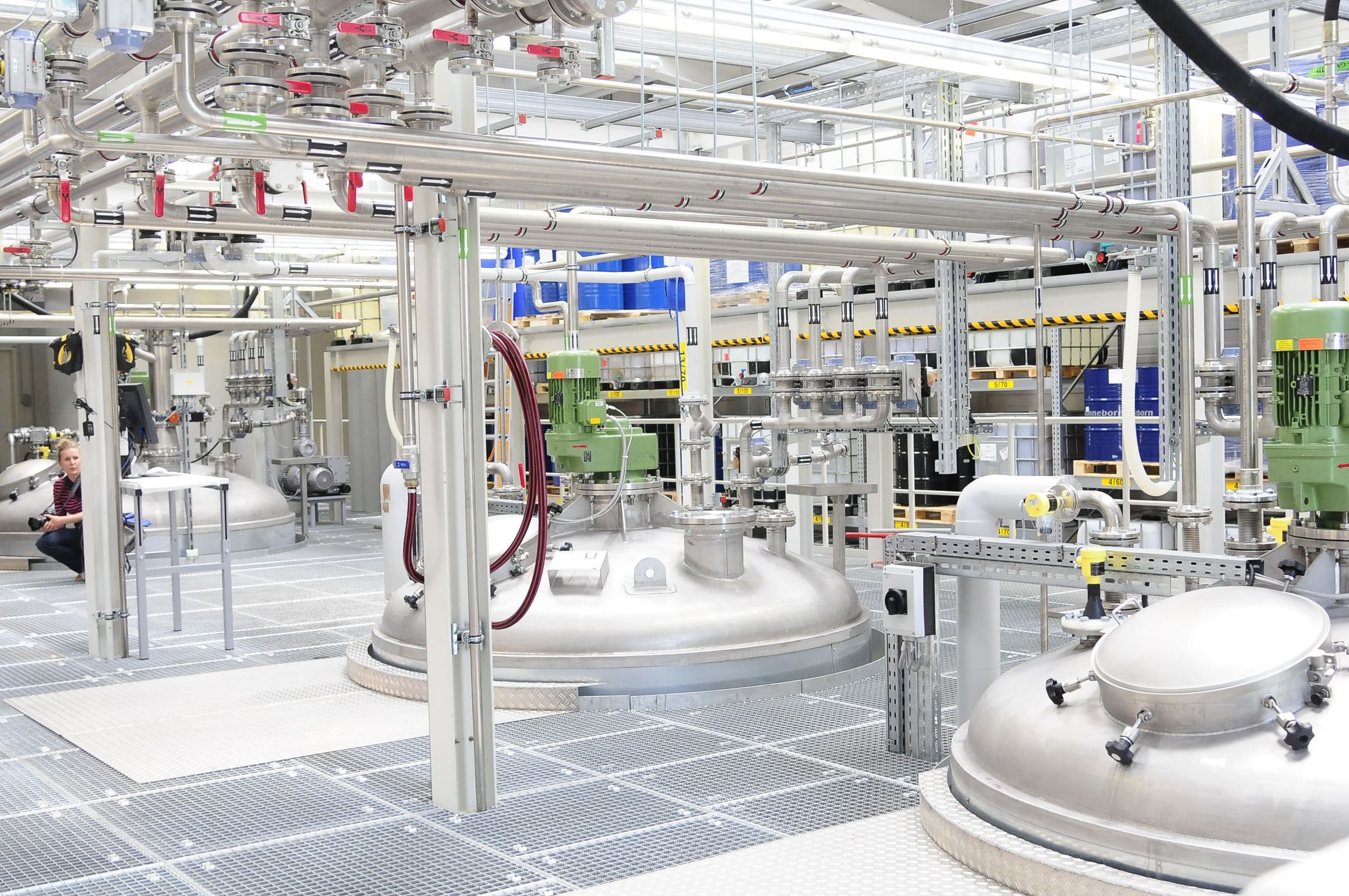
2.1 Heat transfer oil reaction tank system:
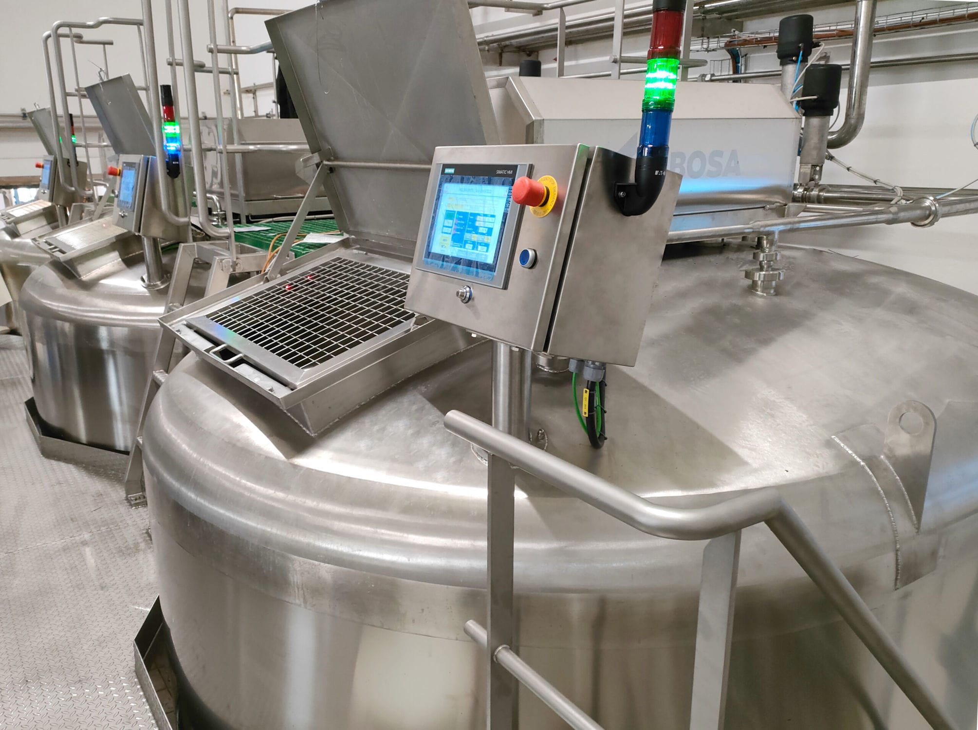
Thermal oil reaction tank dosing mainly has a number (generally 3~4) of thermal oil tank monomer and thermostatic equipment, public valves, to realize the reaction kettle thermal oil supply. In the thermal oil reaction tank dosing system, each monomer has the same equipment composition, each thermal oil reaction tank is a complete and independent functional unit, are able to realize the stirring of the reaction tank, the task of oil delivery; at the same time, they are unified in the thermal oil reaction tank production process under the common cooperation to complete the reaction kettle thermal oil supply work. In addition from the equipment configuration of each thermal oil reaction tank whether instrumentation or electrical equipment configuration is the same;
2.2 reaction tank gas purification (bag) system:
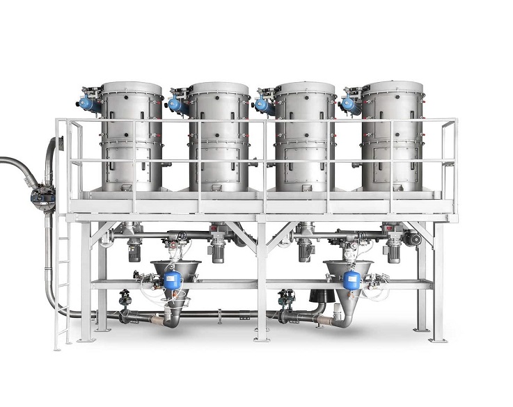
The feeding machine has a number of bags and the main pipe equipment to complete the reaction tank gas purification and supply clean tank gas to the thermal oil reaction tank. Among the composition of the various bags in the single unit is a complete independent function unit, have the same equipment composition, are able to realize the purification, blowback, discharge, send gas task; At the same time are unified in the bag dosage to the reaction tank purification, to the heat transfer oil to send heat preservation state of the production process under.
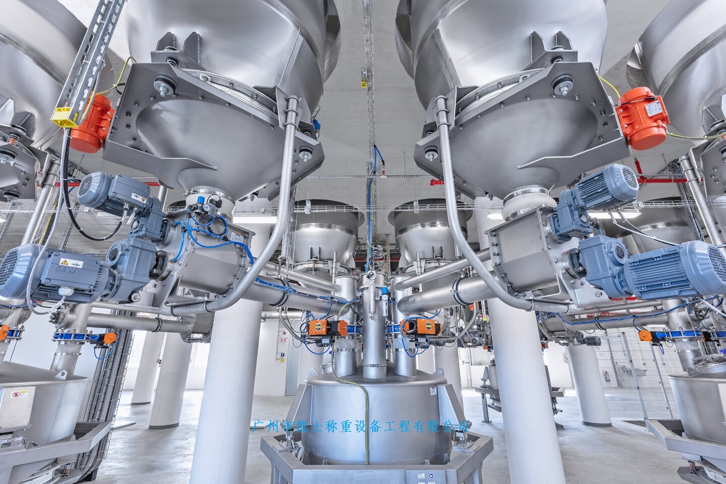
2.3 Frame tank system:
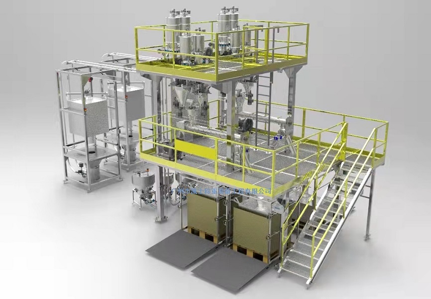
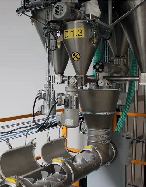
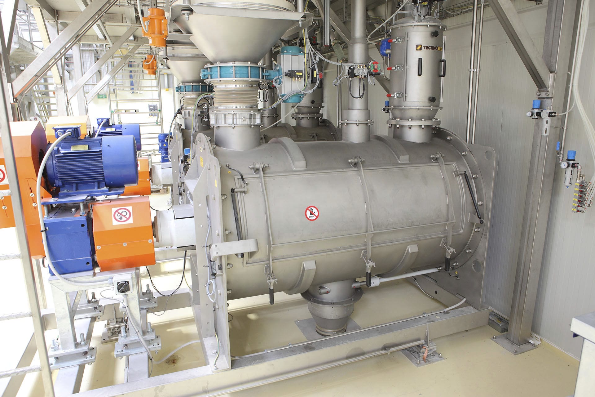
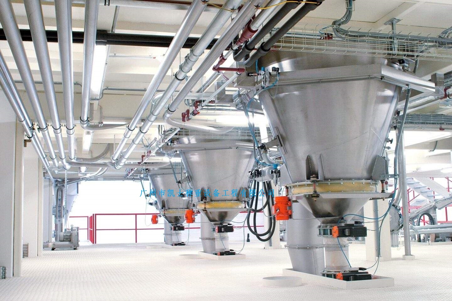
This dosing system consists of feeding belt group, hydraulic station, feeding equipment group, to realize the function of reactor dosing and feeding. Among them, the feeding equipment group consists of silo, down feeder, down vibration sieve, measuring silo, down hydraulic gate dust valve composition, to complete the independent material screening, measuring task, feeding function, engineering dust. And unified under the kettle dosing system to coordinate the work, and jointly complete the kettle feeding production tasks.
It is because of these characteristics of the above three dosage system, for the three dosage system field bus control provides the application of the premise. Thus and the reaction kettle body instrumentation, reaction tank dosage system together constitute the "reaction kettle field bus control plus distributed I / O structure of the automated dosage system".
3、Hardware realization
The total automation configuration structure of the feeding system still retains the existing structure, using three CPUs, which are divided into the control of the reactor body, reactor feed, bag system. At the same time for each dosage for the actual situation, the use of fully distributed I / O structure and fieldbus plus distributed I / O structure. Among them, the reactor body adopts distributed I/O structure, the reaction tank control part (including hydraulic station) in the reactor feeding adopts distributed I/O structure, the frame tank dosage part in the reactor feeding adopts field bus mode, and the heat transfer oil reaction tank and bag adopt field bus mode. The specific configuration is as follows:
3.1 Frame tank dosing:
A master station CUP is shared with the reaction tank, and corresponding S7200 PLC sub-stations are set according to the number of bin groups. Each sub-station communicates with the master CPU through communication to realize data exchange.
Master station functions:
Completes the metering settings for each group of bins and issues dosage commands.
Sub-station functions:
Each sub-station realizes the functions of vibration, metering, discharging, and dust removal; at the same time, it accepts control commands from the master station: metering related setting values, and collaborative dosage commands, and at the same time, it makes corresponding responses. Each sub-station is equipped with an independent control box, which integrates the PLC dosage system, the low voltage system and the instrumentation metering system. Each control box is placed on site. At the same time, the belt group is a separate sub-station.
The dosage system has the following S7200 sub-stations:
11 sets of vibrating material subsystems (14 metering bins are used on site)
Belt feeding system: 1 set
3.2 Reactor gas purification (bag) system:
And thermal oil reaction tank dosage using the same master CPU, and set up the bag single S7200PLC sub-station, the public valve S7200 dosage system, out of the material system S7200 sub-station. Data is exchanged between the sub-stations through communication and the master CPU.I. Fieldbus control concept
Automatic dosage system for the reactor weighing using the traditional cloth I / O structure, for thermal oil tanks, gas purification system, the use of field bus way. In this way the above three feeding system according to the dosage machine in the monomer for the field of small PLC control and electrical control, by the field of PLC to complete the monomer function control and electrical operation, and by the upper level of PLC to realize the production process technology collaboration control. The on-site PLC sub-batching system and the upper level PLC are connected through communication.
In practical terms, the mixer is not a complete fieldbus approach, but draws on the concept of fieldbus field intelligent control, so it is called fieldbus control.
Second, the proposed basis for the program and reliability analysis:
This way of proposing a show in the field equipment to get the characteristics of the basis proposed. Reactor automation is mainly a reactor weighing, reaction tanks, frame tank dosing, bags, thermal oil reaction tank and other system components. In the above feeding system, from the point of view of equipment function and distribution, can be divided into two categories:
1, suitable for distributed I / O structure of the equipment
The first category is the dosage system composed of numerous single-function components or devices. Such as reactor weighing dosage system and reaction tank feeding system belongs to the first category. This category has the equipment dispersed single function and different characteristics. At the same time these devices have a complex dosage system, not suitable for dosage and on-site equipment placed close to the characteristics.
For these devices, the distributed I/O structure is still used.
2、Devices suitable for fieldbus structure
The second category is the dosage system composed of integrated functional equipment. This dosage system is composed of many devices with the same function. They are unified under the overall framework of reactor production, and at the same time they are relatively independent, each sub-unit is a complete small batching system. For example, the frame tank dosage, gas purification (bag), thermal oil reaction tank. These devices are suitable for fieldbus control. They are described in detail below:
2.1 Heat transfer oil reaction tank system:
Thermal oil reaction tank dosing mainly has a number (generally 3~4) of thermal oil tank monomer and thermostatic equipment, public valves, to realize the reaction kettle thermal oil supply. In the thermal oil reaction tank dosing system, each monomer has the same equipment composition, each thermal oil reaction tank is a complete and independent functional unit, are able to realize the stirring of the reaction tank, the task of oil delivery; at the same time, they are unified in the thermal oil reaction tank production process under the common cooperation to complete the reaction kettle thermal oil supply work. In addition from the equipment configuration of each thermal oil reaction tank whether instrumentation or electrical equipment configuration is the same;
2.2 reaction tank gas purification (bag) system:
The feeding machine has a number of bags and the main pipe equipment to complete the reaction tank gas purification and supply clean tank gas to the thermal oil reaction tank. Among the composition of the various bags in the single unit is a complete independent function unit, have the same equipment composition, are able to realize the purification, blowback, discharge, send gas task; At the same time are unified in the bag dosage to the reaction tank purification, to the heat transfer oil to send heat preservation state of the production process under.
2.3 Frame tank system:
This dosing system consists of feeding belt group, hydraulic station, feeding equipment group, to realize the function of reactor dosing and feeding. Among them, the feeding equipment group consists of silo, down feeder, down vibration sieve, measuring silo, down hydraulic gate dust valve composition, to complete the independent material screening, measuring task, feeding function, engineering dust. And unified under the kettle dosing system to coordinate the work, and jointly complete the kettle feeding production tasks.
It is because of these characteristics of the above three dosage system, for the three dosage system field bus control provides the application of the premise. Thus and the reaction kettle body instrumentation, reaction tank dosage system together constitute the "reaction kettle field bus control plus distributed I / O structure of the automated dosage system".
3、Hardware realization
The total automation configuration structure of the feeding system still retains the existing structure, using three CPUs, which are divided into the control of the reactor body, reactor feed, bag system. At the same time for each dosage for the actual situation, the use of fully distributed I / O structure and fieldbus plus distributed I / O structure. Among them, the reactor body adopts distributed I/O structure, the reaction tank control part (including hydraulic station) in the reactor feeding adopts distributed I/O structure, the frame tank dosage part in the reactor feeding adopts field bus mode, and the heat transfer oil reaction tank and bag adopt field bus mode. The specific configuration is as follows:
3.1 Frame tank dosing:
A master station CUP is shared with the reaction tank, and corresponding S7200 PLC sub-stations are set according to the number of bin groups. Each sub-station communicates with the master CPU through communication to realize data exchange.
Master station functions:
Completes the metering settings for each group of bins and issues dosage commands.
Sub-station functions:
Each sub-station realizes the functions of vibration, metering, discharging, and dust removal; at the same time, it accepts control commands from the master station: metering related setting values, and collaborative dosage commands, and at the same time, it makes corresponding responses. Each sub-station is equipped with an independent control box, which integrates the PLC dosage system, the low voltage system and the instrumentation metering system. Each control box is placed on site. At the same time, the belt group is a separate sub-station.
The dosage system has the following S7200 sub-stations:
11 sets of vibrating material subsystems (14 metering bins are used on site)
Belt feeding system: 1 set
3.2 Reactor gas purification (bag) system:
And thermal oil reaction tank dosage using the same master CPU, and set up the bag single S7200PLC sub-station, the public valve S7200 dosage system, out of the material system S7200 sub-station. Data is exchanged between the sub-stations through communication and the master CPU.


