


 2020.03.09


Summary:The polyvinyl alcohol automatic batching system uses Maker to complete the design of the human-machine interface, including functions such as process display, alarms, reports, and historical trends.
The automatic dosage system adopts the cutting-edge electronic technology, control technology, modern control theory, absorbing the strengths of various automatic dosage so far, and it is a small dosage which integrates and synthesizes the functions of intelligent meter, multifunctional loop controller, sequence controller and programmable controller. With advanced control strategy, graphical operation interface and online real-time configuration tool, it realizes real-time monitoring, recording, operation, management of industrial process and its synthesis of continuous control, logical control and sequential control, and it is a new type of computerized automatic dosage system realizing the conception of complex and diversified industrial automation in various industries, which is especially suitable for the enterprise to set up automatic dosage system and the technical transformation of control equipment.
There is no essential difference between CAS800 operator station and engineer station in terms of hardware and software, that is to say, both of them can be common. If there is any difference, it is the software dongle used by both of them is different.
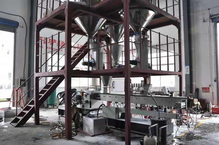
The control station is the core part of CAS800 small-scale automatic batching. The control station is equipped with double redundancy function of power supply, control and communication, which can realize non-disturbance switching in case of any part of the failure to improve the stability and reliability of the automatic batching system and ensure the continuity of production.
The number of I/O design of PVA batching line generates the hardware configuration of the control station as shown in the table below. As CAS800 automatic batching has the feature that universal conditioning template can be mixed and inserted with various I/O modules, which brings great flexibility to the engineering design, users can reasonably arrange the distribution of I/O modules according to the importance of I/O points.
This automatic feeding system is also equipped with an uninterruptible power supply (220V/5KVA, 30min) and a black-and-white laser printer (HPLJ1010) for printing reports.The software configuration of the CAS800 automatic dosage system mainly consists of three parts: real-time database (RDB), algorithmic editing (IEC) and man-machine interface (Maker).
Real-time database is the core of the whole automatic dosage system, all the control algorithms, interfaces, etc. are working around this core.RDB functions mainly include control template settings, I/O acquisition settings and real-time database establishment.
Real-time database is mainly divided into physical I/O and logical I/O, the so-called physical I/O is the data collected by the hardware, such as all the I/O templates and the information transmitted between the field devices. Logical I/O is the data automatically generated by the automatic dosage system through certain operations, such as the cumulative value of the flow rate.IEC is an important part of Tech's industrial control application software platform, which is used to program the control scheme.IEC provides five kinds of control languages conforming to the IEC61131-3 standard, namely, function block diagrams, ladder diagrams, sequential function diagrams, structured text and instruction tables, and has a variety of simulation means, which can greatly improve the engineering and simulation of the project. simulation means, which can greatly improve the progress of the project. Charging ratio control is one of the most important automatic dosages in the alcoholysis section, and the application effect of this control loop directly affects the stability of the production of the device and the quality of the product. Taking resin flow as the main parameter, the resin flow and alkali flow are controlled in a certain range and in a fixed proportional relationship through ratio operation. The program can be realized very easily with FBD control language.
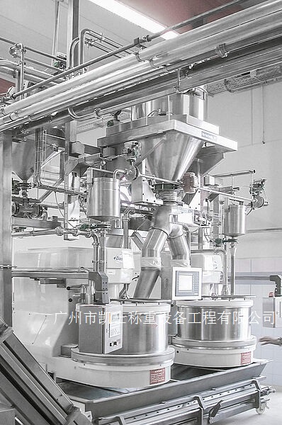
The weighing and loading system keeps the temperature of the resin in the mixer within a certain range through the thermoregulation of the resin preheater. Two lines of warm and cold water are introduced to the resin preheater, with the cold water running when the resin temperature is above a given value and the warm water running when the resin temperature is below a given value. For this purpose, we constructed the split-range regulation loop shown in the figure below.
In the configuration, the output of the PID function block is connected to two TPROC function blocks and the upper and lower limits of the two TPROC function blocks are set to 0/50 and 50/100 respectively, and then output to the two regulating valves through the limit function block. The advantage of this is that the inputs of the two regulating valve positioners are all 4-20mA and do not have to be adjusted to 4-12mA and 12-20mA respectively.
The automatic feeding system is completed with a human-machine interface through Maker, including process display, alarms, reports, and historical trends. The software's built-in gallery contains hundreds of graphical elements. Six filling modes, twenty-four transition color ways, and arbitrary color settings enable users to create process screens according to their preferences. Any graphical elements can be used as display or operation objects, similar to Excel's report design, five types of fourteen kinds of built-in controls and more than one hundred and seventy general-purpose controls, giving programmers a great deal of imagination, so that the original boring engineering configuration has become a pleasant enjoyment.