2020.08.18


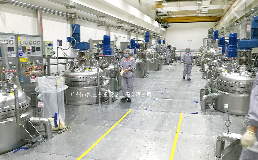
Summary:The batching system integrates raw material batching and the production line of mixing, grinding, crushing and other control objects. It is realized through the computer distributed control system itself. It performs correction, compensation, algorithm and establishes a control system composed of IPC and network communication.
With the DCS feeding system widely used with the rapid development of fieldbus technology, with interoperability, interchangeability, replaceability, expandability (value-added) and multiple support (portability). In terms of the function of the dosage system, more algorithms are required to be implemented, higher control objectives are achieved, and the function of the automatic dosage system is more integrated. In terms of self-diagnostic function of the weighing system, the self-diagnostic function is required to be perfect and accurate. Other aspects, such as ease of operation, reliability and low cost of the dosage system are more demanding. In this case, the powder production process and production management presents such trends as.
(1) The automation level of control is getting higher and higher, from the classical PID regulation, feedback, feed-forward loop control gradually to batch control, centralized control, object-oriented optimization control, artificial intelligence expert control, fuzzy control, self-learning function, etc., and the control of a single parameter and a single target gradually develops to multi-parameter and multi-objective control, taking into account the effects of multiple perturbations to correct and compensate for them. Algorithms and the establishment of a knowledge base is becoming more and more complex, more and more to do a lot of detailed work, and is particularly important.
(2) raw material batching, powder batching and mixing, grinding, crushing and other object optimization control, adaptive control or artificial intelligence expert system, the requirements of the computer through the centralized control system itself, that is, no longer attached to other computer hardware. At present, the use of IPC and network communication control system, the requirements of the system dosage system support software is not only how powerful and rich in content, but its user redevelopment capabilities with different objects of the demand is becoming increasingly important. Batching system software such as support for a variety of popular high-level language, the user according to the different requirements of each special control object can realize their own control strategies, that will be targeted at the industry's software development, the batching system content and the improvement of the software provides an important means.
(3) The site of intelligent weighing instruments are commonly used.
(4) digital DC speed control, variable frequency controller, soft start devices, switching components will be rapidly and widely used.
(5) Manual intervention is less and less, the point of operation is more and more centralized, the operation mode is more and more software.
(6) The function of the control system is more and more to the comprehensive development, the role of CRT is getting stronger and stronger.
(7) digital signals more and more in-depth field, control will be further decentralized, the impact of the failure point will be less and less, the control system investment will be greatly reduced.
(8) enterprise management information system (MIS), enterprise resource planning (ERP) and other information management technology has been successfully applied in a number of advanced powder enterprises, enterprise management information technology and production process control integration is also being rapidly developed, e-commerce is also changing the enterprise's business, management mode to play its growing role.
In recent years, the automatic dosage system process has also undergone major changes, such as the large mill group mixing process, large diameter mixing of the hourly output has also increased substantially, roller mill, vertical mill, high-yield and high-fine mill, high-efficiency powder selector and small pre-homogenization yard and other high-performance equipment and process technology, has been widely used in the mixer powder enterprises; dust collection equipment, efficient and durable are to the mixer to open up a broad Prospects, especially the continuity of production will be greatly improved, which gives the application of automation has laid a new foundation, but also can draw on some of the successful experience of the mixer plant. It is to be compatible with the development of batching technology, batching production line can not be without automation; can not be without computer control system; can not be without efficient and modern digital information management system; and more can not be without high reliability of the detection and measurement system.