
 2023.06.29
Summary:According to the principle of frequency conversion speed regulation and the production process requirements of the automatic batching system, the system uses PID adjustment for actual flow control. The parameters are set according to the frequency converter operating mode to achieve the purpose of automatically adjusting the speed of the belt scale and making the batching The batching accuracy and stability of the system are improved, achieving satisfactory control effects.
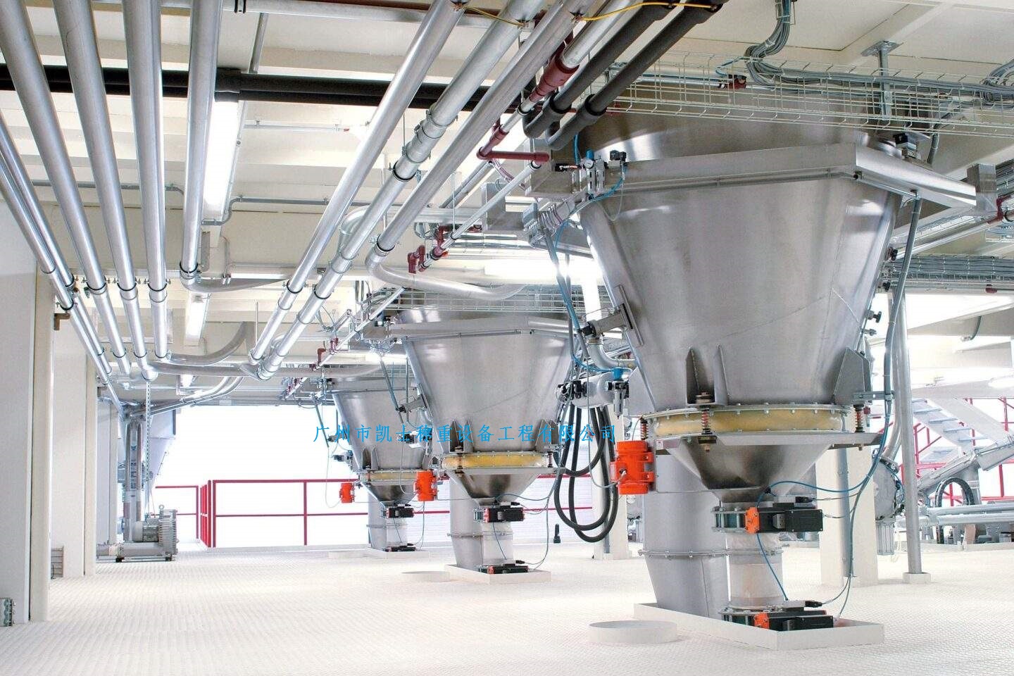
Dosing is a very important process in the production process of fine chemical plant, the backward dosing system is not only low efficiency and dosing is not allowed, manual operation will be introduced into the dosing process, so that the process formula is difficult to be realized in the production, seriously affecting the stability of product quality and further improve the quality of the product, so the realization of high-precision automated dosing of the production of industrial enterprises is of great significance. The original dosage system adopts analog circuit to control the slip motor speed control method, due to the slip motor speed control method in low-speed characteristics of poor, low efficiency, the site of the external working environment is very harsh, industrial dust is a lot of dust, these dust is very easy to enter the slip motor internal wear and tear, jamming and other phenomena, maintenance, maintenance trouble, resulting in more faults, affecting the normal production. With the rapid development of computer technology, the original dosage system for technological transformation, stepless variable speed inverter control closed squirrel cage motor speed mode, with programmable controller to control the inverter, the dosage system will be required for the production of raw materials and auxiliary materials in accordance with a certain proportion of the conveyor belt through the conveyor belt in order to improve the dosage system dosage accuracy and stability.
2 Frequency conversion speed regulation principle
2.1 Working principle of frequency conversion speed regulation
When the structure of the motor is not changed, if the frequency of the power supply is continuously adjustable, the synchronous speed of the motor is also continuously adjustable. As the rotor speed of asynchronous motor is always slightly lower than the synchronous speed, when it is continuously adjustable, it is also continuously adjustable. Therefore, changing the parameters i.e. by changing the power supply frequency can also realize motor speed regulation. When the frequency f is varied within the range of 0 to 50 Hz, the motor speed regulation range is very wide. In fact, just change the frequency of the motor can not get good frequency characteristics, the flux is too weak, not fully utilize the motor flux, is a waste, if you want to increase the flux, and will make the flux saturation, resulting in excessive excitation current, serious damage to the motor because of overheating of the windings. For this reason, in the frequency reduction at the same time also need to reduce the voltage, the need for frequency and voltage coordinated control, that is, variable frequency variable voltage speed control (VVVF), the abbreviation is variable frequency speed control.
2.2 The function of the frequency converter
Frequency converter is a fixed frequency (usually 50HZ) AC power (three-phase or single-phase) into a continuously adjustable frequency (mostly 0 ~ 400Hz) of three-phase AC power. Generally by the rectifier inverter, intermediate circuit, protection circuit and control circuit and other components. Control circuit to complete the control of the main circuit, the rectifier circuit will be converted into direct current, the intermediate circuit of the rectifier circuit to smooth the output filter, inverter circuit will be reversed into alternating current.
3 automatic dosage system control program
3.1 System control program
The system consists of programmable controller and electronic belt scale to form a two-stage computer control network, through the field bus to connect the field instrumentation, control computers, PLC, frequency converter and other high degree of intelligence, fast processing speed equipment. PLC is mainly responsible for system failure detection, display and alarm, and at the same time, output signals to the frequency converter, the frequency converter to complete the role of adjusting the speed of the belt conveyor.
Electronic belt scale weighing is the instantaneous flow, the host computer gives the set flow, the two in real-time measurement deviation. Adopt the most widely used in industrial control PID regulation for the actual control of the flow, Figure 2 for the system flow PID closed-loop regulation structure, according to the flow deviation, the use of proportional, integral, differential calculation of the control amount, through the frequency converter to regulate the speed of the electronic belt scale, adjust the amount of feed to make it equal to the set value, to complete the process of automatic dosage.
3.2 System control flow
When the system starts to work, start the batching production line, weighing and real-time measurement by electronic belt scale, CPU calculates the real-time flow rate and cumulative flow rate. On the one hand, according to the proportion of each auxiliary material at the same time mixed and measured, and added according to the recipe process requirements. On the other hand, if there is a deviation between the set flow rate and the actual flow rate, the regulator compares the deviation between the set value and the actual flow rate according to the system control requirements, and then changes the output signal by PID regulation to control the frequency converter to regulate the speed of the conveyor motor, so as to realize the flow rate control.
4 Frequency conversion speed control system composition
4.1 Functional characteristics of Mitsubishi FR-A540 series inverter
Mitsubishi inverter is a high-performance inverter using flux vector control technology, pulse width modulation (PWM) principle and intelligent power module. Its power range is 0.4~315kW.Mitsubishi FR-A540 series inverter has the following features.
(1) with flux vector control technology. The speed range is 1:120 under open-loop control without speed sensor, and 1:1000 under closed-loop control with speed sensor, and the torque is uniform at low-speed rotation.
(2) SPWM principle and intelligent power module (IPM), inverter output power is better, noise is lower, anti-interference performance is stronger.
(3)Deceleration stop function when power failure, built-in PID control function, inverter/industrial frequency switching function and sequence control function.
(4) Fieldbus communication function in line with international standards.
The DCT values in the matrix are zero, and there are some non-zero DCT values. jpeg chose to compress the zero values by using the tour coding method, and this tour coding process has a good compression effect on most of the matrices which consist of zero values.
We encode the 64 quantized DCT coefficients, here the 64 coefficients are divided into two types, qv(0) located in the upper left corner is called the DC component DC, and the other 63 AC components AC, which will be encoded separately. Output of the 64 data code, you can each of the data, according to the "zigzag" sorted sequentially call the following function, in fact, is the buffer encoded value of 0 data, to be non-zero data, that is, to know how many 0 in front of the first few 0, and then the number of 0 and the output of this data code. In this way, the quantization of JPEG has been completed.
(3) Entropy coding
The last step of DCT coding is encoding. Coding is a lossless coding based on the statistical properties of the quantization coefficients, and the commonly used entropy coding methods are tour length coding Hoffman coding and arithmetic coding. In video coding, tour length coding and Hoffman coding are generally used.
The JPEG standard specifies two entropy coding methods: Hoffman coding and arithmetic coding. Entropy coding can be performed in two steps, first converting the DC code and the trip code into a sequence of intermediate symbols, and then assigning variable-length code words to these symbols.
① Intermediate symbol representation for entropy coding
The differential DC coefficients are encoded with two symbols, symbol 1 and symbol 2. symbol 1 represents the information called "length", i.e., the number of bits used to encode the magnitude of the DC coefficients, and symbol 2 represents the magnitude of the DC coefficients.
Similarly, each AC coefficient is encoded with two symbols, symbol 1 and symbol 2. symbol 1 represents two pieces of information called "stroke" and "length". The stroke is the number of consecutive zero-valued AC coefficients that precede the non-zero AC coefficients in the zigzag matrix, and the length is the number of bits used to encode the magnitude of the AC coefficients. The symbol 2 indicates the magnitude of the AC coefficients.
② Entropy coding
Symbol 1 of the DC coefficient is encoded with a variable-length code in Huffman's table, and symbol 2 is encoded with a variable-length integer code, and if it is negative, it is in the form of the complement of the binary. And for AC coefficients the variable length code in Huffman table is used and along with encoding the DC coefficients, symbol 2 is encoded with variable length integer code.
The coding process is repeated until all 63 coefficients have been processed in this manner. If the last AC coefficient is zero, end the code with a block.
3 Conclusion
There are many other compression coding methods that can be realized for digital images in the JPEG standard, and each method has its own advantages and disadvantages. In the multimedia information volume surge, network characteristics and speed are rapidly improved today, the study of efficient and reasonable compression algorithms is also more and more attention, many aspects of the problem is also becoming more and more prominent, such as the complexity of coding, real-time improvement, decoding the rapidity of the improvement as well as the quality of the image recovery issues. What's more, with the increasing amount of information, the quality of information retrieval is also more and more closely related to the compression coding method. These are all problems to be solved. From the current situation of development, it seems that the hybrid image coding method of fractal and wavelet can give full play to the advantages of wavelet and fractal coding to make up for the shortcomings of each other, so it has become an important research direction of image compression, but it is still far from being mature enough to be further improved.


