2025.05.06


Summary:Feeding system through the negative pressure in turn the raw materials into the hopper scale, weighing and transferred to the hopper, to be timed to time, the PLC gives a control signal to close the feeding motor, open the hopper scale discharge port, the raw materials will be sent to the high mixing tank, at this time, the high mixing motor to start. Raw materials in the high mixing tank through the stirring temperature, until the purpose of mixing (synthesis).
In the chemical, mechanical and other industries in the production process, mixing is very important and essential links, the key to mixing is to ensure the accuracy and reliability of the mixing process weighing, as well as in order to achieve the full mix of raw materials to achieve the accuracy of the temperature and measurement of real-time. The use of general-purpose computer control, although the control accuracy can be achieved, but the cost is high, the requirements of the working environment is high, the requirements of the field operator is also high. The use of PLC to achieve mixing control, not only can the mixing process of all aspects of accurate control, but also greatly reduces the cost, can be directly applied to industrial sites, the site operator requirements are not high.
1 system principle
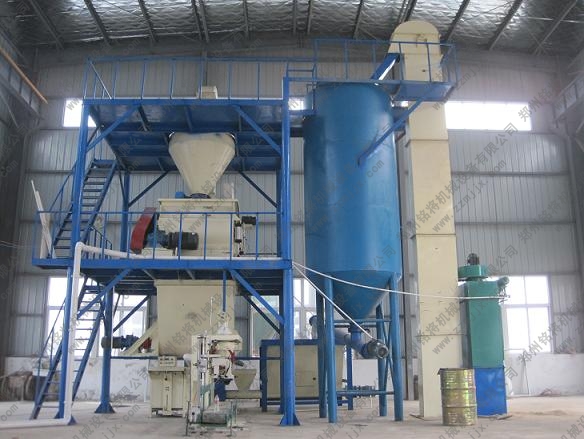
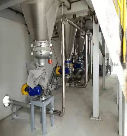
The mixing and feeding system mainly consists of three parts: feeding and weighing, high mixing tank mixing, and cold mixing tank cooling.
Press cycleon (cycle start) button, start feeding, feeding motor start, PLC start timer through the negative pressure will be sucked into the hopper scales, weighing and transferred to the hopper, to be timed to time, the PLC gives a control signal, close the feeding motor, open the hopper scales of the discharge port, the raw materials will be sent to the high mixing tank, at this time, the high mixing motor start. Raw materials in the high mixing tank through the stirring temperature, until it reaches the purpose of mixing (synthesis). In the process of mixing thermocouples will be detected in real time high mixing tank temperature signal value, through the internal A/D converter converted to digital signals, transmitted to the PLC. when the high mixing tank set temperature, PLC sends out a control signal, open the high mixing tank discharge port, the high temperature after the chemical combination of materials into the cold mixing tank. At this time, under the action of PLC control signal, cold mixing motor start, cold mixing pump start water circulation to make the material cooling, thermocouples real-time cold mixing tank temperature signals detected and converted to digital signals, transmitted to the PLC, to reach the set temperature of the cold mixing tank discharge port open, discharge, to complete the process of a mixing.
2 system hardware configuration
In order to achieve control, a large number of switching and analog input and output signals. This feeding system to consider the field signals are: hopper scales in the weighing module detected weight signal analog 1: buttons, selector switches, limit switches and other switching 19, as well as drive solenoid valves, relays, contactors, indicator lights, alarm devices and other switching 21.
Switching-based, only a small amount of analog control system, the current commonly used Siemens S7-200 and OMRON's CQM1. After comparison, chose the former, because of its strong functionality, cost-effective, and provides a variety of different I / O points CPU module and digital, analog I / 0 expansion module for users to choose from, the I / O terminal rows are easy to remove, easy to grasp, easy to operate. The I/O terminal rows are easy to disassemble, easy to grasp and convenient to operate, the specific configuration is as follows:
1) the host for the CPU224 module, a total of 14 inputs integrated I / O outputs count 24 digital I / O points, can be connected to 7 expansion modules, there is a RS485 communication / programming port, the machine has a 24VDC power supply. System due to the switching points, the use of the local I / O. Which, respectively, access to buttons, limit switches, manual switches and other switching input signals, respectively, to drive solenoid valves, relays and other switching output signals.
2) Expand an analog input module 6ES54648MC. It has four analog inputs. The mass mV signal detected by the weighing module in the hopper scale is amplified to the input range of the module, received by ch.0, and then converted into a digital signal, which is sent to the CPU for control through the system bus.
3) Expand a digital input module 6ES54218MA. It has eight inputs, of which pins 1-2 are connected with 24V power supply, and pins 3-10 are respectively connected with the corresponding switch input signals of the cold mixing weighing part. The function of the input module is to convert the level and format of the field signal to form the standard signal needed by the CPU in PLC.
4) Expand three digital output modules 6ES54518MR. It has eight outputs, the common terminal of which is 220V AC voltage, and another 24V DC power supply supplies power for this module. The function of the output module is to convert the standard binary control signal output by the CPU into the control signal required by the production site, which can drive the actions of each actuator, such as driving the corresponding solenoid valve to get electricity in this system.
5) The control panel UNIOP is a liquid crystal display covered keyboard structure. Parameters can be modified online through the menu selection of PageMode, and it can also be used as runtime control to set real-time clock, manual/automatic conversion, alarm and other functions. When connected to the host computer, connect it to the PPI interface of CPU224 module with PC/PPL cable. The above configuration can complete the whole process of mixing control, and the operator only needs to turn on or off the switch/button at the corresponding position on the control cabinet panel and input the corresponding data through the keyboard, and then it can be put into operation.
3 system software design
Step-7-Mico/WIN, a programming software specially designed by Siemens for S7-200 series, is a 32-bit editing software package based on Windows platform. Its user program structure is simple, and users can program in three ways: statement table (STL), ladder diagram (LAD) or function block (FBD). The compiled programs can be converted to each other, which is convenient to use and easy to learn.
The feeding and weighing process, the mixing process in the high mixing tank and the cooling process in the cold mixing tank are called by the main program (monitoring program) as three subprograms. On this basis, STEP7 programming software is used to directly generate and edit ladder diagram, which is convenient for software design and debugging.
4 Conclusion
This batching system has been applied in the production line. It has been running normally for more than a year and achieved good results. The mixing accuracy is accurate and completely meets the design requirements; At the same time, the system has high automation, simple maintenance and convenient use, which reduces the labor intensity of workers. It is believed that this system has certain reference value for the design of feeding system of similar production lines.