2020.01.17


Summary:Polyurethane feeding system control circuit design Based on the automation transformation and engineering expansion of the polyurethane resin (PU) batching system, in view of the problems such as low automation and less visual content in actual batching production, the electrical control circuit was redesigned based on the requirements of the batching process. The comprehensive use of communication technology, PLC technology and WinCC technology constitutes a new wet resin batching system, achieving a high degree of automation and in-depth visualization of the batching process.
Industrial batching is based on a pre-established formula will be a variety of raw materials orderly, quantitative mixing and related processing to form the required products. Batching production is an important and necessary part of industrial production, the quality of the products produced by batching directly affects the normal operation of the subsequent production, the existing batching system through the local testing instrumentation control combined with on-site manual monitoring way to achieve, the labor intensity of workers, the site working environment is harsh, the failure of the maintenance time is long, the accuracy of the process is not up to standard, which leads to low production efficiency, product quality is poor. In terms of the characteristics of the field of industrial batching and its scope of application, the design of the batching control system in accordance with the requirements of the batching process, to realize the automatic and visual batching control system has become one of the important competitive strategy of the current batching industry.
Aiming at the current situation of batching production, in order to improve the labor conditions, optimize the process, improve the production efficiency, and at the same time realize the automation and visualization of the batching process, the authors intend to design a new type of wet resin automatic batching system based on PLC and WinCc, the system design mainly includes the design of the electrical control circuit, PLC program design, WinCc configuration and script program design, the design of the control circuit is the key link of the system design, the control circuit design is the key link of the system design, the control circuit design is the key link of the system design. Control circuit design is the key link in system design, control circuit design not only provides convenience for system software design and on-site installation and debugging, but also lays the electrical foundation for the realization of manual/automatic dual-mode operation of the system. The author focuses on the hardware aspects of the system to introduce the main part of the control circuit design program, and a brief analysis.
1 process introduction
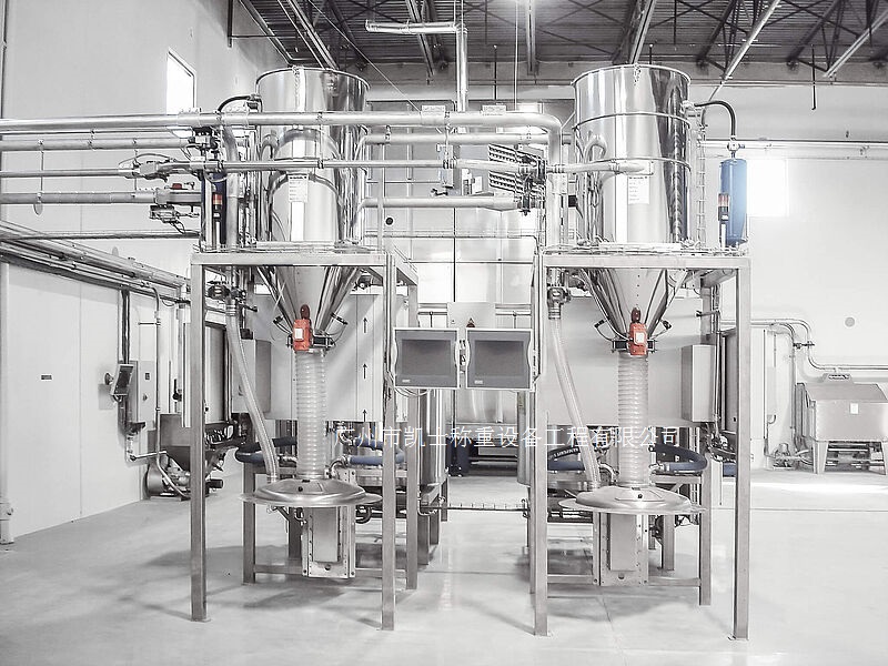
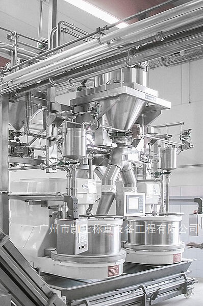
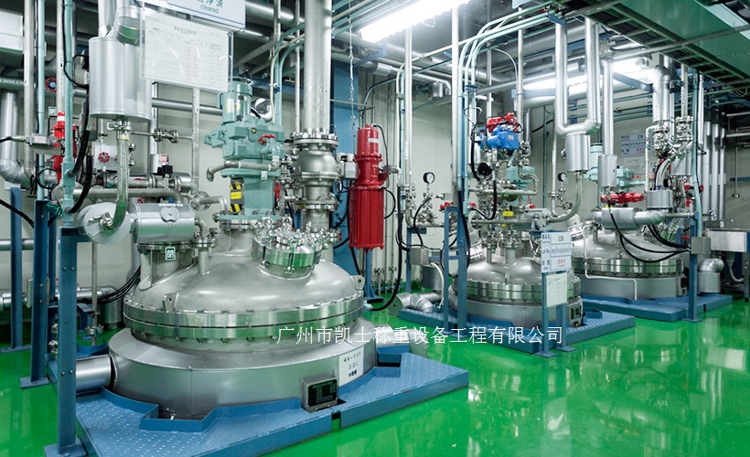
The new wet resin dosing system has a total of 10 kettles (1 ~ 10 kettles) and 5 solvent tanks (1 ~ 5 tanks), of which every 2 kettles share a tank (for example, 1, 2 kettles share 1 tank for solvent dosing). Wet resin dosage formula has 12 kinds of materials (12 material pumps) and 8 kinds of solvents (8 solvent pumps), corresponding to the dosage site of the pipeline is divided into 12 kinds of material pipeline and 8 kinds of solvent pipeline, in the dosage production, according to the formula of a number of materials through the respective pipeline orderly, quantitatively submerged under the selected kettle, through the kettle stirring motor stirring, to reach the standard, the formula required for each solvent were first under the first After reaching the standard, each solvent required by the formula is firstly put into the tank, and after the weighing is qualified and the process conditions are satisfied, the solvent is then put into the selected kettle from the tank to dilute the material in the kettle, and after a series of controllable chemical reactions, the required products are formed.
2 control circuit
2.1 Distribution control circuit
Distribution control circuit design is mainly for the various components of the system safety power supply, in order to ensure the safe and stable operation of control circuits and electrical equipment, the use of 3-level circuit breaker will be divided into a small part of the distribution control circuit is independent of each other, respectively, for each part of the system grading, independent power supply. Where PLC (I) indicates PLC input module, PLC (0) indicates PLC output module.
2.2 Solenoid valve control circuit
Solenoid valve control circuit design is mainly for the control of reaction kettle and solvent tank raw material pipeline solenoid valve on / off, by the dosage process know, each kettle corresponds to 12 material valves, each tank corresponds to 8 solvent valves, material valves and solvent valves are basically the same principle of control, here on the tank valve control circuit is analyzed:
(1) COF1 for the No. 1 tank valve control circuit power circuit breaker;
(2) GSB1 for the No. 1 tank valve control manual/automatic state switch (2 positions: manual, automatic), here for the normally open contacts, its normally closed contacts as a No. 1 tank valve control manual/automatic state switching PLC input signal, for example, when the GSB1 rotated to the manual gear, its normally open contacts closed, that is, the valve control is in a manual state, the No. 1 tank's eight solvent valves can only be controlled through the manual control: on the contrary, when CSB1 rotates to automatic gear, its normally closed contact is closed, the valve control is in automatic state;
(3) corresponding to 1 ~ 8 valve off button (normally closed contacts); corresponding to 1 ~ 8 valve open button (normally open contacts); corresponding to 1 ~ 8 valve valve open status indicator (integrated in the corresponding open button); corresponding to 1 ~ 8 valve valve closed status indicator (integrated in the corresponding off button); corresponding to 1 ~ 8 solenoid valves; the corresponding PLC output relay for the normally open contacts, respectively. In the automatic state, they correspond to the control of No. 1~8 valves.
Tank valve work as an example: when the normally open contact is closed, that is, the manual state, press the line package is powered, its normally open contact is closed, normally closed contact is open, through its own normally open contact self-locking, at this time, the normally closed contact and normally open contact in series with the branch circuit is not accessible, that is, can not be automatic open/close the valve, can only be manually open/close the valve; when the normally closed contact is closed, that is, the automatic state, the line package is not charged, the normally open contact is always disconnected, that is, can not be manually opened/closed valve, then PLC by controlling the state of control valve status to achieve the control of manual and automatic state and manual circuit and automatic circuit interlocking. That can not be manually open/close the valve, at this time the PLC through the control of the state of the line package to achieve the control of the valve state, thus realizing the valve control manual state and automatic state as well as the manual circuit and automatic circuit interlocking. Thus ensure the stability of the system system in addition to material valves and solvent valves, in the bottom of each tank there are 2 discharge valves, they control the direction of solvent discharge in the tank.
Hand/automatic selection of kettle 1 rotary switch (3 positions: stop, manual, automatic), here for the normally open contact; normally closed contact as a hand/automatic kettle 2 PLC input signal, hand/automatic selection of kettle 1 rotary switch (3 positions: stop, manual, automatic) here for the normally open contact; normally closed contact as a hand/automatic selection of kettle 2 PLC input signal; respectively, corresponds to the discharge of material to the 2 kettle solenoid valves, respectively, their corresponding status indicator lamps, the solenoid valves. Respectively for its corresponding status indicator; Respectively corresponds to the PLC output relay normally open contacts, when in the manual selection of kettle No. 1 (or No. 2 kettle) state, once the No. 1 tank weighing qualified signal arrives, normally open contacts closed, the wire packet is electrically charged, its normally open contacts closed, the solenoid valve corresponds to the valve to open, the tank began to No. 1 kettle (or No. 2 kettle) for the material, when in the automatic selection of kettle No. 1 (or No. 2 kettle) state When it is in the state of automatic selecting kettle 1 (or kettle 2), PLC realizes the control on the state of solenoid valve corresponding to the valve respectively by controlling the state of output relay.
2.3 Motor control circuit
The motor control circuit is designed to realize the functions of motor start/stop, thermal protection and high/low speed conversion. According to the dosage process requirements, each kettle is equipped with a stirring motor, the stirring motor also needs to realize the high/low speed operation mode switching, each kettle stirring motor control principle is the same.
The stirring motor high/low speed operation switch (2 positions: high speed, low speed), when FSB1 rotates to the low speed position, the contactor wire pack is electrified (at this time, the two terminals of the contactor wire pack are de-energized), and its normally open contact is closed, the stirring motor is in the low-speed (triangular) operation mode; when it rotates to the high-speed position, the two terminals of the contactor wire pack are electrified, and the corresponding normally open contact is closed, the stirring motor is in the high-speed ( double-star) operation mode. double-star) operation mode.
2.4 Pump control circuit
Pump control circuit is designed to realize the raw material pump on/off, thermal protection and fault alarm function, the system has 12 sets of material pumps and 8 sets of solvent pumps, respectively, on the 10 kettle and 5 solvent tanks for feeding, each pump control principle is basically the same.
The following description and analysis:
(1) B material pump control hand / automatic state switch (2 gears: manual, automatic), here for the normally open contacts, its normally closed contacts as a pump control hand / automatic state switching PLC input signal, through the intermediate relay 4 pairs of contacts to control 1 ~ 4 material pumps, respectively, hand / automatic state switching, when the normally open contacts closed, the pump control is in the manual state; When the normally open contact is open, the pump control When the normally open contact is closed, the pump control is in manual state; when the normally open contact is broken, the pump control is in automatic state. Through the switch and relay can realize 12 sets of material pump hand / automatic state unification, will not appear some pumps in manual state, some pumps in automatic state.
(2) Pump off button, pump on button, pump off status indicator, pump on status indicator; manual state, press the wire package to get power, and through its own normally open contacts to achieve self-locking, then the wire package is powered, the normally open contacts closed, open the pump successfully, the light is on; when the press the wire package is powered off, the pump will be shut down immediately, the light is on. In the automatic state, PLC controls the state of the pump by controlling the state of the output relay.